
Bosch Installation Manual


Examples of Installations
Greenstar – 6721822579 (2021/01)
26
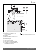
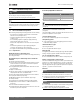
Fig. 10 Wiring
[1] PCB in heating boiler ZBR...-3A
[2] White plug for mains power supply, 120 V AC, 60 Hz
( chapter 7.3.4, page 48)
[3] 120 V AC, 60 Hz
[4] System pump
[5] Red plug for external DHW tank ( chapter 7.3.3, page 48)
[6] DHW pump
[7] External system supply temperature sensor
[8] Motorized valve heating zone 1
[9] Motorized valve heating zone 2
[10] 24 V AC transformer
[11] Outdoor temperature sensor (optional)
[12] LWCO (Low Water Cut Off, 24V AC Transformer required)
[13] DHW temperature sensor (connection with clear connector)
[14] Optionally connect external system supply temperature sensor
for system supply pipe here (with white plug)
For all accessories not included in the package please refer to the Bosch
Product Catalog.
B
B
F
A
6 720 806 992-04.2O
9
8
7
LZ
NZ
4
2
L
N
F
V
L
N
LS NS
0
1
2
3
4
5
6
CZM100
1234
3
4
120 V AC
7 8 9
CRC200
HC1
CRC100
HC2
11
6
5
1
12
14
13
3
2
12
BUSBUS
1212
BUS BUS
1 2
≤ 24 V
NL
N NL NLL
PZ2 PZ3PZ1
1212
T0
24VAC
3412
VZ1
3412
VZ2
34 12
VZ3
≤ 24 V
24 V AC
12
24 V AC
120 V AC
120VAC
120 V AC
MM
10