
installation manual
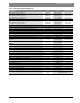
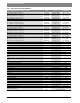
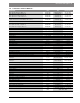
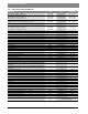
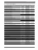

Table Of Contents
- Contents
- 1 Key to symbols and safety instructions
- 1.1 Key to symbols
- 1.2 General safety instructions
- 2 Scope of delivery
- 3 Information about the appliance
- 3.1 Proper use
- 3.2 Overview of boiler types
- 3.3 Rating plate
- 3.4 Appliance description
- 3.5 Accessories
- 3.6 Product dimensions and minimum clearances
- 3.7 Appliance layout heating boiler ZBR..-3A
- 3.8 Appliance layout combi boiler ZWB..-3A
- 3.9 Electrical wiring heating boiler ZBR..-3A
- 3.10 Electrical wiring combi boiler ZWB..-3A
- 3.11 Technical data heating boiler ZBR16-3A...
- 3.12 Technical data heating boiler ZBR21-3A...
- 3.13 Technical data heating boiler ZBR28-3A...
- 3.14 Technical data heating boiler ZBR35-3A...
- 3.15 Technical data heating boiler ZBR42-3A...
- 3.16 Technical data combi boiler ZWB28-3A...
- 3.17 Technical data combi boiler ZWB35-3A...
- 3.18 Technical data combi boiler ZWB42-3A...
- 3.19 Condensate composition
- 4 Regulations
- 5 Installation
- 5.1 Notes on installation and operation
- 5.1.1 Notes on installation and operation
- Fill and make-up water for the heating system
- Recommended steps for commissioning a new or retrofit boiler installation
- Recirculation pump/DHW recirculation lines
- Open vented heating systems
- Gravity heating systems
- Galvanized radiators or pipes.
- Plastic pipework
- Use of a room temperature control
- Water Chemistry Guidelines
- Corrosion inhibitors
- Boiler sealer
- LPG
- 5.1.2 Other important information
- 5.1.1 Notes on installation and operation
- 5.2 Comparing the size of the integrated expansion vessel
- 5.3 ZBR..-3A appliances (heating boilers): Selecting an expansion vessel
- 5.4 Selecting the installation location
- 5.5 Pre-installing pipes
- 5.6 Mounting the appliance
- 5.7 Installing a low water cut off (LWCO)
- 5.8 Connecting flue gas accessories
- 5.9 Testing gas and water connections for leaks
- 5.1 Notes on installation and operation
- 6 Making the electrical connections
- 6.1 General notes
- 6.2 Low voltage electrical connections in the Heatronic boiler control
- 6.3 Electrical connections in the junction box (120 VAC)
- 6.4 Connecting the LWCO device
- 7 Commissioning
- 7.1 Before operating the appliance
- 7.2 Switching the appliance ON/OFF
- 7.3 Setting up space heating
- 7.4 Programming the FW 200 heating control unit
- 7.5 After commissioning
- 7.6 ZBR..-3A appliances (heating boilers) with DHW tank: Setting the DHW temperature
- 7.7 ZWB..-3A appliances (combi boilers): Setting the DHW temperature
- 7.8 Setting manual summer mode
- 7.9 Setting frost protection
- 7.10 Activating the key pad lock
- 8 ZBR..-3A appliances (heating boiler) with DHW tank: Thermal disinfection
- 9 Boiler circulator
- 10 Heatronic boiler control settings
- 10.1 Guideline to service functions
- 10.2 Overview of the service functions
- 10.3 Description of the service functions
- 10.3.1 First service level
- Service function 1.A: Maximum space heating output
- Service function 1.b: Maximum DHW output
- Service function 1.E: Pump mode for space heating operation
- Service function 1. F: Pump mode (only heating boiler ZBR..-3A)
- Service function 2.A: Heating circuit pump lockout time (only heating boiler ZBR..-3A)
- Service function 2.b: Maximum supply temperature
- Service function 2.C: Purging function
- Service function 2.d: Thermal disinfection (legionella protection)
- Service function 2.F: Operating mode
- Service function 3.A: Automatic anti-cycle function
- Service function 3.b: Set anti-cycle time
- Service function 3.C: Switching differential
- Service function 3.d: Minimum output (heating and DHW)
- Service function 3.E: Cycle time, keeping DHW hot (only combi boiler ZWB..-3A)
- Service function 3.F: Constant DHW period (only combi boiler ZWB..-3A)
- Service function 4.b: Maximum heat exchanger temperature (only combi boiler ZWB..-3A)
- Service function 4.d: Audible fault warning tone
- Service function 4.E: Appliance type
- Service function 4.F: Condensate trap filling sequence
- Service function 5.A: Reset inspection interval
- Service function 5.b: Fan post purge time
- Service function 5.E: Functionality of black plug in boiler junction box
- Service function 5.F: Set inspection interval
- Service function 6.A: Display the latest fault code
- Service function 6.b: Room temperature control, current voltage, terminal 2
- Service function 6.C: Supply temperature required by outdoor reset control
- Service function 6.d: Current DHW turbine flow rate (only combi boiler ZWB..-3A)
- Service function 7.A: Indicator lamp for burner operation / faults
- Service function 7.b: 3-way valve in center position
- Service function 7.d: Connecting an external supply or low-loss header temperature sensor
- Service function 7.E: Building drying function
- Service function 0.A: Do not use this setting!
- Service function 0.d: Altitude adjustment
- Service function 0.E: Metric or US customary units
- 10.3.2 Second service level
- Service function 8.A: Software version
- Service function 8.b: Code plug number
- Service function 8.C: GFA Gas burner control unit status
- Service function 8.d: GFA Gas burner control unit fault
- Service function 8.E: Restore boiler to factory settings
- Service function 8.F: Permanent ignition
- Service function 9.A: Constant mode
- Service function 9.b: Current fan speed
- Service function 9.C: Current boiler output
- Service function 9.d: Set fan start speed
- Service function 9.E: Turbine signal delay (only combi boiler ZWB..-3A)
- Service function 9.F: Heating zone pump post purge
- Service function A.b: Display DHW temperature
- Service function A.C: Display DHW tank temperature
- Service function b.F: Solar DHW backup heating delay (only combi boiler ZWB..-3A)
- Service function C.d: Display current heat demand
- 10.3.1 First service level
- 11 Gas type conversion
- 12 Flue gas test
- 13 Environmental responsibility/disposal
- 14 Inspection and maintenance
- Heat exchanger
- Heatronic boiler control
- Notes on installation and operation
- After the inspection/maintenance
- 14.1 Description of various steps
- 14.1.1 Calling up the latest fault (service function 6.A)
- 14.1.2 Fresh water filter (only combi boiler ZWB..-3A)
- 14.1.3 Plate type heat exchanger (only combi boiler ZWB..-3A)
- 14.1.4 Checking the electrodes
- 14.1.5 Burner servicing
- 14.1.6 Heat exchanger block inspection and cleaning
- 14.1.7 Condensate trap cleaning
- 14.1.8 Checking the mixer diaphragm
- 14.1.9 Expansion vessel
- 14.1.10 Setting the boiler water pressure
- 14.1.11 Testing system water quality
- 14.1.12 Inspecting electrical wiring
- 14.2 Checklist for inspection and maintenance
- 15 Readings on the display
- 16 Faults
- 17 Commissioning log for the appliance
- 18 Spare parts
- Index

26 | Regulations
Greenstar6 720 806 992 (2013/07)
3.19 Condensate composition
The condensate volume and ingredients may change with regionally and
seasonally varying gas quality and air quality. Typically the following
ingredients and concentrations can be expected:
4 Regulations
4.1 Compliance with standards and regulations
The installation must conform to the requirements of the authority
having jurisdiction or, in the absence of such requirements, to the latest
edition of the National Fuel Gas Code, ANSI Z223.1./NFPA 54. In
Canada, installation must be in accordance with the requirements of
CAN/CSA B149.1, Natural Gas and Propane Installation Code.
This wall mounted condensing gas boiler complies in its design and
mode of operation with the American National Standard ANSI Z21.13/
CSA4.9, latest edition for Gas Fired Low Pressure Steam and Hot Water
Boilers.
Other confirmed approvals and certifications are indicated by labels on
the boiler.
Where required by the authority having jurisdiction, the installation must
conform to the Standard for Controls and Safety Devices for
Automatically Fired Boilers, ANSI/ASME CSD-1.
Install CO detectors per local regulations. Boiler requires yearly
maintenance ( chapter 14, page 62).
4.2 Operating limits of the boiler
The heat exchanger has been designed and certified in accordance with
the ASME Boiler and Pressure Vessel Code, Section IV.
The hot water distribution system must comply with all applicable codes
and regulations. When replacing an existing boiler, it is important to
check the condition of the entire hot water distribution system to ensure
safe operation. Common practice calls for inspecting an existing system
in its entirety and bringing it up to code. All pipework should be properly
cleaned and flushed.
Condensate
Max. condensate quantity (t
R
= 86 °F (30 °C)) gph (l/h) 0.9 (3.5) 0.9 (3.5)
pH level, approx. – 4.8 4.8
General
Voltage VAC 120 120
Frequency Hz 60 60
Max. power consumption (central heating mode) W 205 205
Max. power consumption (Stand-by) W < 6 < 6
Sound pressure level
dB(A)
45 45
Max. supply temperature °F ( °C) 194 (90) 194 (90)
Max. permissible operating pressure (P
MS
) heating psi (bar) 30 (2.07) 30 (2.07)
Permissible ambient temperature °F ( °C) 32 - 122 (0 - 50) 32 - 122 (0 - 50)
Nominal water capacity (heating) Gal (L) 0.925 (3.5) 0.925 (3.5)
Weight (without packaging) lbs. (kg) 110.2 (50) 110.2 (50)
Dimensions, W x H x D
inch
(mm)
17-21/64" × 33-15/32" × 13-57/64"
(440 × 850 × 353)
Input/Output at elevation 0 - 2000 feet (0 - 610 m) Unit NG LPG (propane)
Table 10 Technical data combi boiler ZWB42-3A...
Substance Value in ppm (mg/l)
Ammonium 1.2
Lead 0.01
Cadmium 0.001
Chrome 0.005
Halogenated hydrocarbons 0.002
Hydrocarbons 0.015
Copper 0.028
Nickel 0.1
Mercury 0.0001
Sulfate 1
Zinc 0.015
Tin 0.01
Vanadium 0.001
pH-value 4.8
Table 11 Typical condensate composition
Observe all rules, regulations, standards and guidelines
applicable to the installation and operation of this
appliance in your country.
In the Commonwealth of Massachusetts, this appliance
must be installed by a licensed plumber and gas fitter.
Valves external to the boiler must be fitted with
T-handles and condensate piping must be installed in
accordance with the State Plumbing Code.
Maximum boiler temperature 194 °F (90 °C)
Maximum operating pressure 30 psi (2.07 bar)
Table 12 Operating limits