
installation manual
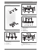
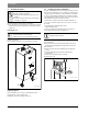
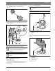
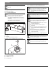
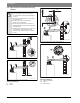
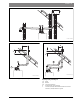
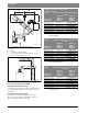
Table Of Contents
- Contents
- 1 Key to symbols and safety instructions
- 1.1 Key to symbols
- 1.2 General safety instructions
- 2 Scope of delivery
- 3 Information about the appliance
- 3.1 Proper use
- 3.2 Overview of boiler types
- 3.3 Rating plate
- 3.4 Appliance description
- 3.5 Accessories
- 3.6 Product dimensions and minimum clearances
- 3.7 Appliance layout heating boiler ZBR..-3A
- 3.8 Appliance layout combi boiler ZWB..-3A
- 3.9 Electrical wiring heating boiler ZBR..-3A
- 3.10 Electrical wiring combi boiler ZWB..-3A
- 3.11 Technical data heating boiler ZBR16-3A...
- 3.12 Technical data heating boiler ZBR21-3A...
- 3.13 Technical data heating boiler ZBR28-3A...
- 3.14 Technical data heating boiler ZBR35-3A...
- 3.15 Technical data heating boiler ZBR42-3A...
- 3.16 Technical data combi boiler ZWB28-3A...
- 3.17 Technical data combi boiler ZWB35-3A...
- 3.18 Technical data combi boiler ZWB42-3A...
- 3.19 Condensate composition
- 4 Regulations
- 5 Installation
- 5.1 Notes on installation and operation
- 5.1.1 Notes on installation and operation
- Fill and make-up water for the heating system
- Recommended steps for commissioning a new or retrofit boiler installation
- Recirculation pump/DHW recirculation lines
- Open vented heating systems
- Gravity heating systems
- Galvanized radiators or pipes.
- Plastic pipework
- Use of a room temperature control
- Water Chemistry Guidelines
- Corrosion inhibitors
- Boiler sealer
- LPG
- 5.1.2 Other important information
- 5.1.1 Notes on installation and operation
- 5.2 Comparing the size of the integrated expansion vessel
- 5.3 ZBR..-3A appliances (heating boilers): Selecting an expansion vessel
- 5.4 Selecting the installation location
- 5.5 Pre-installing pipes
- 5.6 Mounting the appliance
- 5.7 Installing a low water cut off (LWCO)
- 5.8 Connecting flue gas accessories
- 5.9 Testing gas and water connections for leaks
- 5.1 Notes on installation and operation
- 6 Making the electrical connections
- 6.1 General notes
- 6.2 Low voltage electrical connections in the Heatronic boiler control
- 6.3 Electrical connections in the junction box (120 VAC)
- 6.4 Connecting the LWCO device
- 7 Commissioning
- 7.1 Before operating the appliance
- 7.2 Switching the appliance ON/OFF
- 7.3 Setting up space heating
- 7.4 Programming the FW 200 heating control unit
- 7.5 After commissioning
- 7.6 ZBR..-3A appliances (heating boilers) with DHW tank: Setting the DHW temperature
- 7.7 ZWB..-3A appliances (combi boilers): Setting the DHW temperature
- 7.8 Setting manual summer mode
- 7.9 Setting frost protection
- 7.10 Activating the key pad lock
- 8 ZBR..-3A appliances (heating boiler) with DHW tank: Thermal disinfection
- 9 Boiler circulator
- 10 Heatronic boiler control settings
- 10.1 Guideline to service functions
- 10.2 Overview of the service functions
- 10.3 Description of the service functions
- 10.3.1 First service level
- Service function 1.A: Maximum space heating output
- Service function 1.b: Maximum DHW output
- Service function 1.E: Pump mode for space heating operation
- Service function 1. F: Pump mode (only heating boiler ZBR..-3A)
- Service function 2.A: Heating circuit pump lockout time (only heating boiler ZBR..-3A)
- Service function 2.b: Maximum supply temperature
- Service function 2.C: Purging function
- Service function 2.d: Thermal disinfection (legionella protection)
- Service function 2.F: Operating mode
- Service function 3.A: Automatic anti-cycle function
- Service function 3.b: Set anti-cycle time
- Service function 3.C: Switching differential
- Service function 3.d: Minimum output (heating and DHW)
- Service function 3.E: Cycle time, keeping DHW hot (only combi boiler ZWB..-3A)
- Service function 3.F: Constant DHW period (only combi boiler ZWB..-3A)
- Service function 4.b: Maximum heat exchanger temperature (only combi boiler ZWB..-3A)
- Service function 4.d: Audible fault warning tone
- Service function 4.E: Appliance type
- Service function 4.F: Condensate trap filling sequence
- Service function 5.A: Reset inspection interval
- Service function 5.b: Fan post purge time
- Service function 5.E: Functionality of black plug in boiler junction box
- Service function 5.F: Set inspection interval
- Service function 6.A: Display the latest fault code
- Service function 6.b: Room temperature control, current voltage, terminal 2
- Service function 6.C: Supply temperature required by outdoor reset control
- Service function 6.d: Current DHW turbine flow rate (only combi boiler ZWB..-3A)
- Service function 7.A: Indicator lamp for burner operation / faults
- Service function 7.b: 3-way valve in center position
- Service function 7.d: Connecting an external supply or low-loss header temperature sensor
- Service function 7.E: Building drying function
- Service function 0.A: Do not use this setting!
- Service function 0.d: Altitude adjustment
- Service function 0.E: Metric or US customary units
- 10.3.2 Second service level
- Service function 8.A: Software version
- Service function 8.b: Code plug number
- Service function 8.C: GFA Gas burner control unit status
- Service function 8.d: GFA Gas burner control unit fault
- Service function 8.E: Restore boiler to factory settings
- Service function 8.F: Permanent ignition
- Service function 9.A: Constant mode
- Service function 9.b: Current fan speed
- Service function 9.C: Current boiler output
- Service function 9.d: Set fan start speed
- Service function 9.E: Turbine signal delay (only combi boiler ZWB..-3A)
- Service function 9.F: Heating zone pump post purge
- Service function A.b: Display DHW temperature
- Service function A.C: Display DHW tank temperature
- Service function b.F: Solar DHW backup heating delay (only combi boiler ZWB..-3A)
- Service function C.d: Display current heat demand
- 10.3.1 First service level
- 11 Gas type conversion
- 12 Flue gas test
- 13 Environmental responsibility/disposal
- 14 Inspection and maintenance
- Heat exchanger
- Heatronic boiler control
- Notes on installation and operation
- After the inspection/maintenance
- 14.1 Description of various steps
- 14.1.1 Calling up the latest fault (service function 6.A)
- 14.1.2 Fresh water filter (only combi boiler ZWB..-3A)
- 14.1.3 Plate type heat exchanger (only combi boiler ZWB..-3A)
- 14.1.4 Checking the electrodes
- 14.1.5 Burner servicing
- 14.1.6 Heat exchanger block inspection and cleaning
- 14.1.7 Condensate trap cleaning
- 14.1.8 Checking the mixer diaphragm
- 14.1.9 Expansion vessel
- 14.1.10 Setting the boiler water pressure
- 14.1.11 Testing system water quality
- 14.1.12 Inspecting electrical wiring
- 14.2 Checklist for inspection and maintenance
- 15 Readings on the display
- 16 Faults
- 17 Commissioning log for the appliance
- 18 Spare parts
- Index

Installation | 33
6 720 806 992 (2013/07)Greenstar
▶ Screw the LWCO as far as possible into LWCO adapter located in the
boiler accessory kit. Follow the Hydrolevel Safgard 1100
instructions.
Fig. 20 Installing a LWCO device - LWCO adapter
▶ Push the adapter with the LWCO onto the pipe (step 1) and secure
with the clip (step 2).
Fig. 21 Installing a LWCO device – securing with a clip
▶ Connect the wires of the LWCO ( chapter 6.4, page 46).
5.8 Connecting flue gas accessories
Optional vent systems are:
• Twin pipe PVC / CPVC 2" / 3"
• Twin pipe PP 3" (80 mm) (M&G DuraVent PolyPro GreenVent system)
• Concentric PP 3" / 5" (80/125 mm) (M&G DuraVent PolyPro
GreenVent system)
In case of using the twin pipe adaptor:
▶ Install the vent flange and gasket with the screws enclosed.
Fig. 22 Attaching the vent flange and gasket
[1] Gasket
[2] Vent flange
[3] Screws
▶ Insert the flue gas adapter as far as it will go into the vent flange and
align it.
Fig. 23 Flue gas adapter
[1] Vent flange
[2] Flue gas adapter
[3] Combustion air test port
[4] Flue gas test ports
▶ Tighten the screws.
The LWCO is positioned upright for technical reasons.
Tests have shown that all air will bleed from the pipe
during commissioning and full functionality is
established.
If fault d3 is displayed when commissioning the boiler,
purge the boiler properly and check the boiler water
pressure.
6 720 641 933-64.1O
6 720 641 933-65.3O
1
2
Ø
1
Ø
2
Ø
1
> Ø
2
The twin pipe adaptor is supplied with the boiler kit as
standard.
1
2
3
6 720 612 737-01.1O
6 720 641 933-85.1O
3
4
1
2