
installation manual
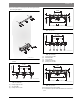
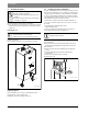
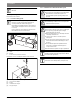
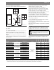
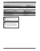
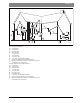
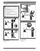
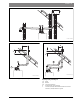
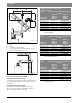
Table Of Contents
- Contents
- 1 Key to symbols and safety instructions
- 1.1 Key to symbols
- 1.2 General safety instructions
- 2 Scope of delivery
- 3 Information about the appliance
- 3.1 Proper use
- 3.2 Overview of boiler types
- 3.3 Rating plate
- 3.4 Appliance description
- 3.5 Accessories
- 3.6 Product dimensions and minimum clearances
- 3.7 Appliance layout heating boiler ZBR..-3A
- 3.8 Appliance layout combi boiler ZWB..-3A
- 3.9 Electrical wiring heating boiler ZBR..-3A
- 3.10 Electrical wiring combi boiler ZWB..-3A
- 3.11 Technical data heating boiler ZBR16-3A...
- 3.12 Technical data heating boiler ZBR21-3A...
- 3.13 Technical data heating boiler ZBR28-3A...
- 3.14 Technical data heating boiler ZBR35-3A...
- 3.15 Technical data heating boiler ZBR42-3A...
- 3.16 Technical data combi boiler ZWB28-3A...
- 3.17 Technical data combi boiler ZWB35-3A...
- 3.18 Technical data combi boiler ZWB42-3A...
- 3.19 Condensate composition
- 4 Regulations
- 5 Installation
- 5.1 Notes on installation and operation
- 5.1.1 Notes on installation and operation
- Fill and make-up water for the heating system
- Recommended steps for commissioning a new or retrofit boiler installation
- Recirculation pump/DHW recirculation lines
- Open vented heating systems
- Gravity heating systems
- Galvanized radiators or pipes.
- Plastic pipework
- Use of a room temperature control
- Water Chemistry Guidelines
- Corrosion inhibitors
- Boiler sealer
- LPG
- 5.1.2 Other important information
- 5.1.1 Notes on installation and operation
- 5.2 Comparing the size of the integrated expansion vessel
- 5.3 ZBR..-3A appliances (heating boilers): Selecting an expansion vessel
- 5.4 Selecting the installation location
- 5.5 Pre-installing pipes
- 5.6 Mounting the appliance
- 5.7 Installing a low water cut off (LWCO)
- 5.8 Connecting flue gas accessories
- 5.9 Testing gas and water connections for leaks
- 5.1 Notes on installation and operation
- 6 Making the electrical connections
- 6.1 General notes
- 6.2 Low voltage electrical connections in the Heatronic boiler control
- 6.3 Electrical connections in the junction box (120 VAC)
- 6.4 Connecting the LWCO device
- 7 Commissioning
- 7.1 Before operating the appliance
- 7.2 Switching the appliance ON/OFF
- 7.3 Setting up space heating
- 7.4 Programming the FW 200 heating control unit
- 7.5 After commissioning
- 7.6 ZBR..-3A appliances (heating boilers) with DHW tank: Setting the DHW temperature
- 7.7 ZWB..-3A appliances (combi boilers): Setting the DHW temperature
- 7.8 Setting manual summer mode
- 7.9 Setting frost protection
- 7.10 Activating the key pad lock
- 8 ZBR..-3A appliances (heating boiler) with DHW tank: Thermal disinfection
- 9 Boiler circulator
- 10 Heatronic boiler control settings
- 10.1 Guideline to service functions
- 10.2 Overview of the service functions
- 10.3 Description of the service functions
- 10.3.1 First service level
- Service function 1.A: Maximum space heating output
- Service function 1.b: Maximum DHW output
- Service function 1.E: Pump mode for space heating operation
- Service function 1. F: Pump mode (only heating boiler ZBR..-3A)
- Service function 2.A: Heating circuit pump lockout time (only heating boiler ZBR..-3A)
- Service function 2.b: Maximum supply temperature
- Service function 2.C: Purging function
- Service function 2.d: Thermal disinfection (legionella protection)
- Service function 2.F: Operating mode
- Service function 3.A: Automatic anti-cycle function
- Service function 3.b: Set anti-cycle time
- Service function 3.C: Switching differential
- Service function 3.d: Minimum output (heating and DHW)
- Service function 3.E: Cycle time, keeping DHW hot (only combi boiler ZWB..-3A)
- Service function 3.F: Constant DHW period (only combi boiler ZWB..-3A)
- Service function 4.b: Maximum heat exchanger temperature (only combi boiler ZWB..-3A)
- Service function 4.d: Audible fault warning tone
- Service function 4.E: Appliance type
- Service function 4.F: Condensate trap filling sequence
- Service function 5.A: Reset inspection interval
- Service function 5.b: Fan post purge time
- Service function 5.E: Functionality of black plug in boiler junction box
- Service function 5.F: Set inspection interval
- Service function 6.A: Display the latest fault code
- Service function 6.b: Room temperature control, current voltage, terminal 2
- Service function 6.C: Supply temperature required by outdoor reset control
- Service function 6.d: Current DHW turbine flow rate (only combi boiler ZWB..-3A)
- Service function 7.A: Indicator lamp for burner operation / faults
- Service function 7.b: 3-way valve in center position
- Service function 7.d: Connecting an external supply or low-loss header temperature sensor
- Service function 7.E: Building drying function
- Service function 0.A: Do not use this setting!
- Service function 0.d: Altitude adjustment
- Service function 0.E: Metric or US customary units
- 10.3.2 Second service level
- Service function 8.A: Software version
- Service function 8.b: Code plug number
- Service function 8.C: GFA Gas burner control unit status
- Service function 8.d: GFA Gas burner control unit fault
- Service function 8.E: Restore boiler to factory settings
- Service function 8.F: Permanent ignition
- Service function 9.A: Constant mode
- Service function 9.b: Current fan speed
- Service function 9.C: Current boiler output
- Service function 9.d: Set fan start speed
- Service function 9.E: Turbine signal delay (only combi boiler ZWB..-3A)
- Service function 9.F: Heating zone pump post purge
- Service function A.b: Display DHW temperature
- Service function A.C: Display DHW tank temperature
- Service function b.F: Solar DHW backup heating delay (only combi boiler ZWB..-3A)
- Service function C.d: Display current heat demand
- 10.3.1 First service level
- 11 Gas type conversion
- 12 Flue gas test
- 13 Environmental responsibility/disposal
- 14 Inspection and maintenance
- Heat exchanger
- Heatronic boiler control
- Notes on installation and operation
- After the inspection/maintenance
- 14.1 Description of various steps
- 14.1.1 Calling up the latest fault (service function 6.A)
- 14.1.2 Fresh water filter (only combi boiler ZWB..-3A)
- 14.1.3 Plate type heat exchanger (only combi boiler ZWB..-3A)
- 14.1.4 Checking the electrodes
- 14.1.5 Burner servicing
- 14.1.6 Heat exchanger block inspection and cleaning
- 14.1.7 Condensate trap cleaning
- 14.1.8 Checking the mixer diaphragm
- 14.1.9 Expansion vessel
- 14.1.10 Setting the boiler water pressure
- 14.1.11 Testing system water quality
- 14.1.12 Inspecting electrical wiring
- 14.2 Checklist for inspection and maintenance
- 15 Readings on the display
- 16 Faults
- 17 Commissioning log for the appliance
- 18 Spare parts
- Index

Installation | 35
6 720 806 992 (2013/07)Greenstar
Direct vent installations (sealed combustion)
For direct vent applications all applicable items below must be met.
Fig. 26 Vent and combustion air pipe position of a sealed combustion
system
[1] Intake
[2] Exhaust
X At least 1 foot (305 mm)
The termination shall terminate at least 1 foot (305 mm) below, 1 foot
(305 mm) horizontally from or 1 foot (305 mm) above any door,
window or gravity air inlet into any building ( fig. 27 [2], [X
1
], [X
3
],
page 37).
If multiple boilers are installed in a row, allow at least 1 foot (305 mm)
clearance between the vent termination of one and the combustion air
intake of the other.
Vent termination must be at least 1 foot (305 mm) above grade,
anticipated snow line or roof surface (Canada
1-1/2 feet (457 mm) minimum) ( fig. 27 [Y
A
], page 37).
Vent termination must be at least 7 feet (2135 mm) above a public
walkway ( fig. 27 [X
5
], page 37). Ensure that condensate spilling
from the termination does not create a hazard or a nuisance.
Vent termination must be 3 feet (915 mm) above any forced air intake
within 10 feet (3 050 mm) ( fig. 27 [1], [Y
B
], page 37).
Do not extend exposed vent pipe outside the building beyond
recommended distance. Condensate could freeze and block vent pipe.
Vent should terminate at least 3 feet (915 mm) away from adjacent
walls, inside corners and 5 feet (1 525 mm) below roof overhang
( fig. 27 [X
2
], [X
4
], page 37).
It is not recommended to terminate vent above any door or window,
condensate can freeze causing ice formations.
Do not use chimney as a raceway if another boiler or fireplace is vented
into or through chimney.
All PVC/CPVC vent pipes must be glued, except for the flue gas adapter-
pipe connection.
All PP/PVC/CPVC combustion air and vent pipe materials and fittings
must comply with the following and must be UL approved venting
material:
X
X
XX
1
2
6 720 641 933-19.1O
The exhaust pipe must be properly supported and
pitched a minimum of ¼ inch (6.35 mm) per foot back to
the boiler. This allows the condensate to properly drain.
NOTICE: Damage of 2 inch PVC pipes.
▶ For ZBR42-3A and ZWB42-3A use 2 inch CPVC-pipes
or 3 inch pipes.
Material Item United states Canada
ZBR16-3A
ZBR28-3A
ZBR35-3A
ZBR42-3A
ZWB28-3A
ZWB35-3A
ZWB42-3A
PVC schedule 40, 80
2" (50 mm) Vent or
air pipe and fitting
ANSI/ASTM D1785
BH Gas venting
systems,
ULC S636
1)
1) Components of the certified vent systems must not be interchanged with other vent systems or unlisted pipe fittings. Plastic components, and specified primers and glues of
the certified vent system must be from a single system manufacturer and not intermixed with other system manufacturer's vent system parts.
XXX XX
PVC-DWV ANSI/ASTM D2665 XXX XX
CPVC schedule 40, 80 ANSI/ASTM F441 XXXXXXX
PVC schedule 40, 80
3" (76 mm) Vent or
air pipe and fitting
ANSI/ASTM D1785 XXXXXXX
PVC-DWV ANSI/ASTM D2665 XXXXXXX
CPVC schedule 40, 80 ANSI/ASTM F441 XXXXXXX
PP
3" (80 mm) vent or
air pipe M&G/
DuraVent PolyPro
GreenVent
ANSI Cat IV XXXXXXX
PP ANSI Cat IV XXXXXXX
PP
3"/5" (80/125 mm)
concentric M&G/
DuraVent PolyPro
GreenVentt
ANSI Cat IV XXXXXXX
PP ANSI Cat IV XXXXXXX
PVC
Pipe cement/primer
ANSI/ASTM D2564 XXXXXXX
CPVC ANSI/ASTM F493 XXXXXXX
Table 17 Materials for pipe