
installation manual
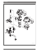
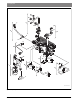
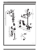

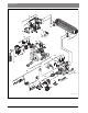
Table Of Contents
- Contents
- 1 Key to symbols and safety instructions
- 1.1 Key to symbols
- 1.2 General safety instructions
- 2 Scope of delivery
- 3 Information about the appliance
- 3.1 Proper use
- 3.2 Overview of boiler types
- 3.3 Rating plate
- 3.4 Appliance description
- 3.5 Accessories
- 3.6 Product dimensions and minimum clearances
- 3.7 Appliance layout heating boiler ZBR..-3A
- 3.8 Appliance layout combi boiler ZWB..-3A
- 3.9 Electrical wiring heating boiler ZBR..-3A
- 3.10 Electrical wiring combi boiler ZWB..-3A
- 3.11 Technical data heating boiler ZBR16-3A...
- 3.12 Technical data heating boiler ZBR21-3A...
- 3.13 Technical data heating boiler ZBR28-3A...
- 3.14 Technical data heating boiler ZBR35-3A...
- 3.15 Technical data heating boiler ZBR42-3A...
- 3.16 Technical data combi boiler ZWB28-3A...
- 3.17 Technical data combi boiler ZWB35-3A...
- 3.18 Technical data combi boiler ZWB42-3A...
- 3.19 Condensate composition
- 4 Regulations
- 5 Installation
- 5.1 Notes on installation and operation
- 5.1.1 Notes on installation and operation
- Fill and make-up water for the heating system
- Recommended steps for commissioning a new or retrofit boiler installation
- Recirculation pump/DHW recirculation lines
- Open vented heating systems
- Gravity heating systems
- Galvanized radiators or pipes.
- Plastic pipework
- Use of a room temperature control
- Water Chemistry Guidelines
- Corrosion inhibitors
- Boiler sealer
- LPG
- 5.1.2 Other important information
- 5.1.1 Notes on installation and operation
- 5.2 Comparing the size of the integrated expansion vessel
- 5.3 ZBR..-3A appliances (heating boilers): Selecting an expansion vessel
- 5.4 Selecting the installation location
- 5.5 Pre-installing pipes
- 5.6 Mounting the appliance
- 5.7 Installing a low water cut off (LWCO)
- 5.8 Connecting flue gas accessories
- 5.9 Testing gas and water connections for leaks
- 5.1 Notes on installation and operation
- 6 Making the electrical connections
- 6.1 General notes
- 6.2 Low voltage electrical connections in the Heatronic boiler control
- 6.3 Electrical connections in the junction box (120 VAC)
- 6.4 Connecting the LWCO device
- 7 Commissioning
- 7.1 Before operating the appliance
- 7.2 Switching the appliance ON/OFF
- 7.3 Setting up space heating
- 7.4 Programming the FW 200 heating control unit
- 7.5 After commissioning
- 7.6 ZBR..-3A appliances (heating boilers) with DHW tank: Setting the DHW temperature
- 7.7 ZWB..-3A appliances (combi boilers): Setting the DHW temperature
- 7.8 Setting manual summer mode
- 7.9 Setting frost protection
- 7.10 Activating the key pad lock
- 8 ZBR..-3A appliances (heating boiler) with DHW tank: Thermal disinfection
- 9 Boiler circulator
- 10 Heatronic boiler control settings
- 10.1 Guideline to service functions
- 10.2 Overview of the service functions
- 10.3 Description of the service functions
- 10.3.1 First service level
- Service function 1.A: Maximum space heating output
- Service function 1.b: Maximum DHW output
- Service function 1.E: Pump mode for space heating operation
- Service function 1. F: Pump mode (only heating boiler ZBR..-3A)
- Service function 2.A: Heating circuit pump lockout time (only heating boiler ZBR..-3A)
- Service function 2.b: Maximum supply temperature
- Service function 2.C: Purging function
- Service function 2.d: Thermal disinfection (legionella protection)
- Service function 2.F: Operating mode
- Service function 3.A: Automatic anti-cycle function
- Service function 3.b: Set anti-cycle time
- Service function 3.C: Switching differential
- Service function 3.d: Minimum output (heating and DHW)
- Service function 3.E: Cycle time, keeping DHW hot (only combi boiler ZWB..-3A)
- Service function 3.F: Constant DHW period (only combi boiler ZWB..-3A)
- Service function 4.b: Maximum heat exchanger temperature (only combi boiler ZWB..-3A)
- Service function 4.d: Audible fault warning tone
- Service function 4.E: Appliance type
- Service function 4.F: Condensate trap filling sequence
- Service function 5.A: Reset inspection interval
- Service function 5.b: Fan post purge time
- Service function 5.E: Functionality of black plug in boiler junction box
- Service function 5.F: Set inspection interval
- Service function 6.A: Display the latest fault code
- Service function 6.b: Room temperature control, current voltage, terminal 2
- Service function 6.C: Supply temperature required by outdoor reset control
- Service function 6.d: Current DHW turbine flow rate (only combi boiler ZWB..-3A)
- Service function 7.A: Indicator lamp for burner operation / faults
- Service function 7.b: 3-way valve in center position
- Service function 7.d: Connecting an external supply or low-loss header temperature sensor
- Service function 7.E: Building drying function
- Service function 0.A: Do not use this setting!
- Service function 0.d: Altitude adjustment
- Service function 0.E: Metric or US customary units
- 10.3.2 Second service level
- Service function 8.A: Software version
- Service function 8.b: Code plug number
- Service function 8.C: GFA Gas burner control unit status
- Service function 8.d: GFA Gas burner control unit fault
- Service function 8.E: Restore boiler to factory settings
- Service function 8.F: Permanent ignition
- Service function 9.A: Constant mode
- Service function 9.b: Current fan speed
- Service function 9.C: Current boiler output
- Service function 9.d: Set fan start speed
- Service function 9.E: Turbine signal delay (only combi boiler ZWB..-3A)
- Service function 9.F: Heating zone pump post purge
- Service function A.b: Display DHW temperature
- Service function A.C: Display DHW tank temperature
- Service function b.F: Solar DHW backup heating delay (only combi boiler ZWB..-3A)
- Service function C.d: Display current heat demand
- 10.3.1 First service level
- 11 Gas type conversion
- 12 Flue gas test
- 13 Environmental responsibility/disposal
- 14 Inspection and maintenance
- Heat exchanger
- Heatronic boiler control
- Notes on installation and operation
- After the inspection/maintenance
- 14.1 Description of various steps
- 14.1.1 Calling up the latest fault (service function 6.A)
- 14.1.2 Fresh water filter (only combi boiler ZWB..-3A)
- 14.1.3 Plate type heat exchanger (only combi boiler ZWB..-3A)
- 14.1.4 Checking the electrodes
- 14.1.5 Burner servicing
- 14.1.6 Heat exchanger block inspection and cleaning
- 14.1.7 Condensate trap cleaning
- 14.1.8 Checking the mixer diaphragm
- 14.1.9 Expansion vessel
- 14.1.10 Setting the boiler water pressure
- 14.1.11 Testing system water quality
- 14.1.12 Inspecting electrical wiring
- 14.2 Checklist for inspection and maintenance
- 15 Readings on the display
- 16 Faults
- 17 Commissioning log for the appliance
- 18 Spare parts
- Index

Spare parts | 81
6 720 806 992 (2013/07)Greenstar
Item ( Fig. 96) Designation
ZBR16-3A
ZBR21-3A
ZBR28-3A
ZBR35-3A
ZBR42-3A
ZWB28-3A
ZWB35-3A
ZWB42-3A
Order number
1 Heat exchanger block (incl. set of gaskets) incl. flue gas and
condensate collector (item 4)
8 737 701 797 0
2 Nut 8 713 301 196 0
3 Set of gaskets 8 710 103 206 0
4 Flue gas and condensate collector 8 718 006 944 0
5 Temperature limit sensor 8 722 963 858 0
6 Return pipe nut and safety pin 8 719 928 487 0
7 Temperature sensor 8 714 500 087 0
8 Cover 8 711 000 262 0
9 Gasket 8 710 103 153 0
10 Shield 8 718 003 836 0
11 Clip (10x) 8 710 100 190 0
12 Set of electrodes complete 8 718 107 089 0
13 Flame viewing window 8 715 600 018 0
14 Gasket (10) 8 711 004 264 0
15 Burner 8 718 006 658 0
16 Burner gasket 8 711 004 168 0
17 Top burner cover complete 8 715 416 029 0
18 Attachment nuts, washers, safety pins (set of 2) 8 710 305 296 0
19 Gasket 8 729 000 183 0
20 Bracket 8 718 005 603 0
21 Attachment bolt complete 8 710 305 297 0
22 Temperature limiter assy 8 710 506 267 0
23 Heat exchanger gasket 8 710 103 155 0
Table 46 Group 2 - Burner/Heat exchanger Greenstar