
Bosch Installation Manual


Notes on installation and operation
37
Greenstar – 6721822579 (2021/01)
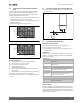
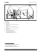
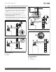
If multiple boilers are installed in a row, allow at least 1 foot (305 mm)
clearance between the vent termination of one and the combustion air
intake of the other.
The combustion air inlet is located at least 1 ft (305 mm) above the
upper edge, the expected snow line or roof surface (in Canada, at least 1
1/2 ft (457 mm) ( Fig. 31 [Y
A
], page 31).
Vent termination must be located at least 7 ft (2135 mm) above public
traffic routes ( fig. 31 [X
5
], page 31). Condensate can exit at the
terminal end. Ensure that condensate spilling from the termination does
not create a hazard or a nuisance.
Do not allow expose vent pipes outside the building to extend past the
recommended distance. Condensate can freeze and block the flue
outlet.
Vent termination must be at least 3 ft (915 mm) away from adjoining
walls, inside corners and 5 ft (525 mm) below the roof overhang
( Fig. 31 [X
2
], [X
4
], page 31).
Do not extend exposed vent pipe outside the building beyond
recommended distance. Condensate could freeze and block vent pipe.
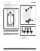
Did not use the chimney as a conduit if the flue gases from a wall-
mounted gas condensing boiler or other combustion equipment are
routed in or through the chimney.
All non-steel PVC/CPVC vent pipes must be glued, except for the flue gas
adapter.
The flue pipe must be supported properly and angled downward at least
¼ inch (6.35 mm) per foot from the wall-mounted gas condensing boiler.
This allows the condensate to drain away.
NOTICE
Damage of 2 inch PVC pipes.
▶ For ZBR 42-3 A and ZWB 42-3 A use 2 inch CPVC-pipes or 3 inch
pipes.
All PP/PVC/CPVC combustion air and vent pipe materials and fittings
must be approved and comply with the following:
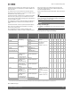
Table 14 Materials for pipe
Material Item United states Canada
ZBR 21-3 A
ZBR 28-3 A
ZBR 35-3 A
ZBR 42-3 A
ZWB 28-3 A
ZWB 35-3 A
ZWB 42-3 A
PVC schedule 40, 80 2" (50 mm) Vent or air
pipe and fitting
ANSI/ASTM D1785 or
UL 1738
BH Gas venting systems,
ULC S636
a
,
Class IIA - PVC,Class IIB -
CPVC,Class IIC -
Polypropylene
(certified to ULC S636)
a. Components of the certified vent systems must not be interchanged with other vent systems or unlisted pipe fittings. Plastic components, and specified primers and glues
of the certified vent system must be from a single system manufacturer and not intermixed with other system manufacturer's vent system parts.
XXX XX
PVC-DWV ANSI/ASTM D2665 or
UL 1738
XXX XX
CPVC schedule 40, 80 ANSI/ASTM F441 or
UL 1738
XXXXXXX
PVC schedule 40, 80 3" (76 mm) Vent or air
pipe and fitting
ANSI/ASTM D1785 or
UL 1738
XXXXXXX
PVC-DWV ANSI/ASTM D2665 or
UL 1738
XXXXXXX
CPVC schedule 40, 80 ANSI/ASTM F441 or
UL 1738
XXXXXXX
PP rigid venting 3" (80 mm) vent or air
pipe M&G Duravent
PolyPro and
Centrotherm InnoFlue
ANSI Cat IV
Approved Polypropylene
XXXXXXX
PP rigid venting 2" (50 mm) vent or air
pipe M&G Duravent
PolyPro and
Centrotherm InnoFlue
ANSI Cat IV
Approved Polypropylene
XXXXXXX
PP rigid venting 3"/5" (80/125 mm)
concentric (Bosch,
manufactured by M&G
Duravent)
ANSI Cat IV
Approved Polypropylene
XXXXXXX
PP-Flex 3" (80 mm) vent or air
pipe M&G Duravent
PolyPro and
Centrotherm InnoFlue
ANSI Cat IV
Approved Polypropylene
BH Gas venting systems,
ULC S636
a.
,
Class IIA - PVC,Class IIB -
CPVC,
Class IIC - Polypropylene
(certified to ULC S636)
XXXXXXX
PP-Flex 2" (50 mm) vent or air
pipe M&G Duravent
PolyPro and
Centrotherm InnoFlue
ANSI Cat IV
Approved Polypropylene
XXX XX
PVC Pipe cement/primer ANSI/ASTM D2564 X X X X X X X
CPVC ANSI/ASTM F493 XXXXXXX