
Bosch Installation Manual


Notes on installation and operation
Greenstar – 6721822579 (2021/01)
40
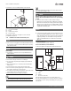
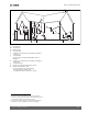
6.8.2 Examples of approved horizontal and vertical venting installation
NOTICE
▶ Place pipe supports every 5 ft (1525 mm) of horizontal and vertical
run, beginning with support near wall-mounted gas condensing
boiler.
▶ Remove condensate in accordance with applicable regulations.
▶ Regularly clean the vent terminal and safety mesh.
▶ Avoid locating vent terminal near equipment or items that could be
adversely affected by flue gases.
▶ When installing several appliances in a row, maintain a clearance of at
least 1 ft (305 mm) between the vent terminal of one appliance and
the combustion air inlet of the next appliance.
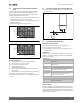
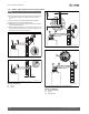
Fig. 32 Horizontal venting system (room air only)
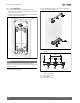
Fig. 33 Horizontal venting system (room air only)
Key to Fig. 32 and Fig. 33:
[1] Intake
[2] Exhaust
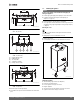
Fig. 34 Horizontal venting system (sealed combustion)
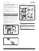
Fig. 35 Horizontal venting system (sealed combustion)
Key to Fig. 34 and Fig. 35:
[1] Intake, behind exhaust
[2] Exhaust
[3] Wall termination
6 720 641 933-06.2O
21
2
6 720 641 933-62.2O
2
1
≥ 4"
(102 mm)
2
6 720 641 933-63.2O
1
2
1
2
≥ 4"
(102 mm)
≥ 12"
(305 mm)
6 720 641 933-05.2O
1
2
3