IMPORTANT: Read Before Using IMPORTANT : Lire avant usage IMPORTANTE: Leer antes de usar Operating/Safety Instructions Consignes d’utilisation/de sécurité Instrucciones de funcionamiento y seguridad AG40-85 AG40-85P AG40-85PD AG40-11P AG40-11PD AG50-10 AG50-11VS AG50-11VSPD AG50-125PD AG60-125 AG60-125PD Call Toll Free for Consumer Information & Service Locations Pour obtenir des informations et les adresses de nos centres de service après-vente, appelez ce numéro gratuit Llame gratis para obtener in
General Power Tool Safety Warnings Read all safety warnings and all instructions. Failure to follow the warnings ! WARNING and instructions may result in electric shock, fire and/or serious injury. SAVE ALL WARNINGS AND INSTRUCTIONS FOR FUTURE REFERENCE The term “power tool” in all of the warnings refers to your mains-operated (corded) power tool or battery-operated (cordless) power tool.
Power tool use and care Keep handles dry, clean and free from oil and grease. Slippery hands cannot safely control the power tool. Do not force the power tool. Use the correct power tool for your application. The correct power tool will do the job better and safer at the rate for which it was designed. Use clamps or other practical way to secure and support the workpiece to a stable platform. Holding the work by hand or against your body is unstable and may lead to loss of control.
Develop a periodic maintenance schedule for your tool. When cleaning a tool be careful not to disassemble any portion of the tool since internal wires may be misplaced or pinched or safety guard return springs may be improperly mounted. Certain cleaning agents such as gasoline, carbon tetrachloride, ammonia, etc. may damage plastic parts. at maximum no-load speed for one minute. Damaged accessories will normally break apart during this test time. Wear personal protective equipment.
direct guard opening or particles toward your body. Such preventive safety measures reduce the risk of injury while operating the tool. Never place your hand near the rotating accessory. Accessory may kickback over your hand. A type 27 guard must be used with all grinding wheels, bonded body sanding flap discs, wire brushes and wheels. The tool may be used without a guard only when sanding with conventional sanding discs.
Additional Safety Warnings Specific for Abrasive Cutting-Off Operations: Do not “jam” the cut-off wheel or apply excessive pressure. Do not attempt to make an excessive depth of cut. Overstressing the wheel increases the loading and susceptibility to twisting or binding of the wheel in the cut and the possibility of kickback or wheel breakage. the sanding pad presents a laceration hazard and may cause snagging, tearing of the disc or kickback.
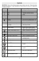
Symbols IMPORTANT: Some of the following symbols may be used on your tool. Please study them and learn their meaning. Proper interpretation of these symbols will allow you to operate the tool better and safer. Symbol Name Designation/Explanation V Volts Voltage (potential) A Amperes Current Hz Hertz Frequency (cycles per second) W Watt Power kg Kilograms Weight min Minutes Time s Seconds Time Diameter Size of drill bits, grinding wheels, etc.
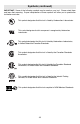
Symbols (continued) IMPORTANT: Some of the following symbols may be used on your tool. Please study them and learn their meaning. Proper interpretation of these symbols will allow you to operate the tool better and safer. This symbol designates that this tool is listed by Underwriters Laboratories. This symbol designates that this component is recognized by Underwriters Laboratories. This symbol designates that this tool is listed by Underwriters Laboratories, to United States and Canadian Standards.
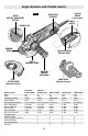
Angle Grinders with Paddle Switch FIG. 1 LOCK-ON SWITCH (select models) VENTILATION OPENINGS GUARD RELEASE / ADJUSTMENT BUTTON PADDLE SWITCH SPINDLE LOCK GRINDING WHEEL "LOCK-OFF" SWITCH RELEASE LEVER TYPE 27 GRINDING GUARD VIBRATION CONTROL SIDE HANDLE TYPE 1 CUTTING GUARD (Optional Accessory) Model number Amps Volts Rated speed (RPM) Spindle thread Max. grinding wheel dia. Max. cutting wheel Max. sanding disc Max. flap disc Max. wire wheel Max.
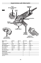
Angle Grinders with Slide Switch VENTILATION OPENINGS GUARD RELEASE / ADJUSTMENT BUTTON FIG. 2 SPINDLE LOCK SLIDE SWITCH GRINDING WHEEL TYPE 27 GRINDING GUARD VIBRATION CONTROL SIDE HANDLE TYPE 1 CUTTING GUARD (Optional Accessory) Model number Amps Volts Rated speed (RPM) Spindle thread Max. grinding wheel dia. Max. cutting wheel Max. sanding disc Max. flap disc Max. wire wheel Max.
Application Model number Metal Grinding (Type 27) Metal Grinding (Type 11) Metal Grinding (Type 1) Metal Cutting Concrete Surfacing Concrete/Masonry Cutting Sanding Wire Brushing (Wheel) Wire Brushing (Cup) AG40-85 X N N O O O O X O Model number Metal Grinding (Type 27) Metal Grinding (Type 11) Metal Grinding (Type 1) Metal Cutting Concrete Surfacing Concrete/Masonry Cutting Sanding Wire Brushing (Wheel) Wire Brushing (Cup) AG40-11P(D) X N N O O O O X O AG50-10 X N N O O O O X O AG50-11VS X N N O O O O
Functional Descriptions Electronic Clutch: The electronics in the power tool detects situations where the wheel or accessory may be at risk to bind. The electronics prevents further rotation of the drive spindle by switching the power tool off (it does not prevent kickback). To resume operation, turn on/off switch to the off position, then restart tool. Constant Response Circuitry: Helps maintain near constant RPMs between no-load and load conditions.
Installing Wheel Guards FIG. 5 (Type 27 & Type 1 Wheel Guards) A Type 27 guard must be ! WARNING used with all grinding wheels, bonded body sanding flap discs, wire brushes and wheels. The tool may be used without a guard only when sanding with conventional sanding discs. To attach guard (Fig. 5): WHEEL GUARD SPINDLE NECK 1. Unplug tool from power source. 2. Position appropriate guard on spindle neck so arrows on guard and spindle neck align. 3.
Abrasive Type 27 Grinding Wheel & Sanding Flap Disk Assembly FIG. 7 Your tool is equipped with a threaded spindle for mounting non-threaded hub accessories. Always use the supplied backing flange with a lock nut. Always ensure that arbor diameter matches accessory diameter. SPINDLE To install grinding wheel or flap disk (Fig. 7): TYPE 27 WHEEL GUARD 1. Unplug tool from power source. BACKING FLANGE 2. Install and adjust type 27 grinding guard to the proper position for grinding as shown in figure 5.
Abrasive Type 1 & 27 Cutting Wheel Assembly FIG. 9 Always use type 1 cutting for cutting operations. Other guards or attachments may not protect operator in the event of a wheel burst. ! WARNING guard SPINDLE A type 27 wheel guard may ! WARNING not be used for all tool operations. Do not discard guard when not in use. Always reinstall wheel guard when converting back to grinding operations. TYPE 1 WHEEL GUARD To install cutting wheel (Fig. 9): 1. Unplug tool from power source. BACKING FLANGE 2.
Concrete Dust Extraction Attachment for Surfacing Grinding Assembly FIG. 10 A type 27 grinding wheel ! WARNING guard may not be used for all tool operations. Do not discard guard when not in use. Always reinstall wheel guard when converting back to grinding operations. Dust SPINDLE Extraction ! WARNING Attachment is not a guard, do not use with bonded abrasive wheels. Dust extraction attachment may not protect operator in the event of a wheel burst.
Sanding Assembly A type 27 wheel guard may FIG. 11 ! WARNING not be used for all tool operations. Do not discard guard when not in use. Always reinstall wheel guard when converting back to grinding operations. The hand shield is to be used with backing pads, sanding discs and wire brushes to keep fingers and hand away from work surface, sharp edges, burs and debris. When using the hand shield accessory, insert side handle through hole in shield and then thread into housing (Fig 4).
Masonry Cutting Guard Assembly FIG. 13 4x A type 27 grinding wheel ! WARNING guard may not be used for all tool operations. Do not discard guard when not in use. Always reinstall wheel guard when converting back to grinding operations. To improve ergonomics of your grinder when cutting masonry, gearbox must be rotated relative to the position of the switch as the tool was assembled at the factory. m 0m Rotate gearbox (Fig. 13): 1. Unplug tool from power source. 2.
6. Screw in side handle to secure stability bracket between the tool housing and handle. FIG. 15 SPINDLE 7. Adjust guard to desired depth of cut. DRY DIAMOND WHEEL TO REMOVE: Reverse procedure. Installing dry diamond wheel (Fig. 15): 1. Place the backing flange on the spindle. Turn flange until it locks with the base of the spindle. LOCK NUT 2. Place the dry diamond wheel onto the spindle and align the arbor hole of the grinding wheel with the shoulder of the backing flange. BACKING FLANGE 3.
Operating Instructions If the “Lock-ON” button is being depressed, the trigger cannot be released. LOCK-ON SWITCH ! WARNING continuously Never leave the trigger "ON". Before plugging the tool in, check that the trigger lock is "OFF". Accidental start-ups could cause injury. FIG. 17 ! WARNING locked Be aware of the location ! WARNING and setting of the switch "Lock-ON" button. If the switch is locked "ON" during the use, be ready for emergency situations to switch it "OFF".
Metal Grinding FIG. 19 Grinding wheels should be carefully selected in order to use the grinder most efficiently. Wheels vary in type of abrasive, bond, hardness, grit size and structure. The correct wheel to use is determined by the job. Use disc grinding wheels for fast grinding of structural steel, heavy weld beads, steel casting, stainless steel and other ferrous metals. 1. Allow the tool to reach full speed before touching the tool to the work surface. 2.
Masonry / Concrete Cutting With this grinder it is possible to perform cutting of concrete and masonry materials. When cutting, work with moderate feed, adapted to the material being cut. FIG. 21 Always follow precautions for kickback. Operate the tool with a dust extraction system and personal dust protection, e.g. respirator, dust mask, etc. The vacuum used for this application must be approved for the extraction of masonry and concrete dust. Bosch sells suitable vacuum cleaners.
Concrete Surfacing Operate the tool with a dust extraction system and personal dust protection, e.g. respirator, dust mask, etc. The vacuum used for this application must be approved for the extraction of masonry and concrete dust. Bosch sells suitable vacuum cleaners. Diamond cup wheels should be carefully selected in order to use the grinder most efficiently. Wheels vary in type of material they are designed to remove and how aggressively they will remove material.
Wire Brush (Wheels and Cups) FIG. 24 Wire brushes are intended to “clean” structural steel, castings, sheet metal, stone, and concrete. They are used to remove rust, scale, and paint. 1. Allow the tool to reach full speed before touching the tool to the work surface. 2. Apply minimum pressure to the work surface, allowing the tool to operate at high speed. 3. Continuously move the tool at a moderate speed to avoid creating gouges in the work surface. 4.
Maintenance Service Preventive maintenance ! WARNING performed by unauthorized per so n nel may result in misplacing of internal wires and components which could cause serious hazard. We recommend that all tool service be performed by a Bosch Factory Service Center or Authorized Bosch Service Station. GFCI and personal protection devices like electrician’s rubber gloves and footwear will further enhance your personal safety. TOOL LUBRICATION Your Bosch tool has been properly lubricated and is ready to use.
Avertissements généraux concernant la sécurité des outils électroportatifs Veuillez lire tous les ! AVERTISSEMENT avertissements et toutes les consignes de sécurité. Si l'on n'observe pas ces avertissements et ces consignes de sécurité, il existe un risque de choc électrique, d'incendie et/ou de blessures corporelles graves. CONSERVEZ TOUS LES AVERTISSEMENTS ET TOUTES LES CONSIGNES DE SÉCURITÉ POUR RÉFÉRENCE FUTURE.
Utilisation et entretien des outils électroportatifs Si vous sentez une résistance lorsque vous utilisez l’outil électroportatif, ne forcez pas. Utilisez l’outil électroportatif qui convient pour la tâche à effectuer. C’est en utilisant l’outil le plus approprié que vous obtiendrez de meilleurs résultats, et il est toujours plus sûr de travailler à la vitesse pour laquelle l’outil a été conçu.
Réparations Faites réparer votre outil électroportatif par un technicien compétent n’utilisant que des pièces de rechange identiques. Ceci assurera le maintien de la sécurité de l’outil électroportatif. Une maintenance préventive effectuée par des personnes non autorisées pourrait causer un placement inapproprié de fils et composants internes constituant un danger grave.
l’accessoire pourrait s’accrocher à la surface et attirer l’outil électroportatif en vous en faisant perdre le contrôle. Ne laissez pas l’outil électroportatif fonctionner pendant que vous le transportez à côté de vous. Un contact accidentel avec l’accessoire en train de tourner pourrait accrocher vos vêtements et attirer cet accessoire vers une partie de votre corps. Nettoyez périodiquement les évents d’aération de l’outil électroportatif.
rotation de la meule, et il pourrait être difficile de désactiver la fonction de verrouillage de la gâchette en position de marche. Avertissements concernant la sécurité pour les opérations de meulage et de tronçonnage abrasif : Utilisez seulement des types de meules qui sont recommandés pour votre outil électroportatif et le protège-meule qui a été conçu spécifiquement pour la meule sélectionnée.
Avertissements concernant la sécurité pour les opérations de passage à la brosse métallique : Avertissements additionnels : Certaines Gardez à l’esprit que des soies sont fortement susceptibles de se détacher et d’être éjectées par la brosse même pendant des opérations ordinaires. Évitez d’appliquer une charge excessive sur la brosse car vous risqueriez d’exercer une pression excessive sur les soies. Les soies peuvent facilement pénétrer dans les vêtements légers et/ou la peau.
Symboles IMPORTANT : Certains des symboles suivants peuvent être utilisés sur votre outil. Veuillez les étudier et apprendre leur signification. Une interprétation appropriée de ces symboles vous permettra d'utiliser l'outil de façon plus efficace et plus sûre.
Symboles (suite) IMPORTANT : Certains des symboles suivants peuvent être utilisés sur votre outil. Veuillez les étudier et apprendre leur signification. Une interprétation appropriée de ces symboles vous permettra d'utiliser l'outil de façon plus efficace et plus sûre. Ce symbole signifie que cet outil est approuvé par Underwriters Laboratories. Ce symbole indique que ce composant est reconnu par Underwriters Laboratories.
Meuleuses d’angles avec interrupteur à palette FIG.
Angle Grinders with Slide Switch ÉVENTS DE VENTILATION BOUTON DE RÉGLAGE/DE DÉSACTIVATION DU DISPOSITIF DE PROTECTION FIG. 2 VERROUILLAGE DE L’ARBRE INTERRUPTEUR COULISSANT MEULE PROTÈGE-MEULE DE TYPE 27 POIGNÉE LATÉRALE DE CONTRÔLE DES VIBRATIONS DISPOSITIF DE PROTECTION POUR OUTIL DE COUPE DE TYPE 1 (Accessoire en option) Model number Ampères Volts Vitesse (tr/min) Filet de l’arbre Diam. max. de la meule Molette de coupe max. Disque de ponçage max. Disque abrasif à surface agglomérée max.
Application Modèle N° AG40-85 Meulage de métaux (Type 27) X Meulage de métaux (Type 11) N Meulage de métaux (Type 1) N Coupe de métaux O Surfaçage des sols en béton O Coupe de béton/maçonnerie O Ponçage O Passage à la brosse métallique(meule) X Passage à la brosse métallique(boisseau) O Modèle N° Meulage de métaux (Type 27) Meulage de métaux (Type 11) Meulage de métaux (Type 1) Coupe de métaux Surfaçage des sols en béton Coupe de béton/maçonnerie Ponçage Passage à la brosse métallique(meule) Passage à la br
Descriptions fonctionnelles Embrayage électronique : L’électronique de l’outil électroportatif détecte les situations dans lesquelles la meule ou l’accessoire peut risquer de se coincer. Elle empêche la poursuite de la rotation de l’arbre d’entraînement en mettant l’outil hors tension (mais elle ne peut pas empêcher les effets de rebond). Pour recommencer à travailler, mettez l’interrupteur de marche/arrêt (on/off) dans la position de marche (on) et remettez l’outil en marche.
Installation des dispositifs de protection des meules FIG. 5 (Protège-meule de type 27 et de type 1) Un protège-meule de type ! AVERTISSEMENT 27 doit être utilisé avec toutes les meules abrasives, disques abrasifs à surface agglomérée, brosses métalliques et autres meules. L’outil ne peut être utilisé sans dispositif de protection que lors d’opérations de ponçage avec des disques de ponçage conventionnels. Fixation du dispositif de protection (Fig. 5) : PROTÈGE -MEULE COL DE L’ARBRE 1.
Montage de la meule abrasive de type 27 et du disque de ponçage FIG. 7 Votre outil est équipé d’un arbre fileté permettant de monter des accessoires non filetés. Utilisez toujours la contre-bride fournie avec un écrou de blocage. Veillez toujours à ce que le diamètre de l’arbre corresponde à celui de l’accessoire. ARBRE Installation de la meule abrasive ou du disque de ponçage (Fig. 7) : 1. Débranchez l’outil de sa source d’alimentation électrique. PROTÈGEMEULE DE TYPE 27 CONTREBRIDE 2.
Montage de molettes abrasives de types 1 et 27 Utilisez toujours FIG. 9 un ! AVERTISSEMENT dispositif de protection de type 1 pour les opérations de coupe. Les autres accessoires ou dispositifs de protection ne protégeront peut-être pas aussi bien l’opérateur en cas d’éclatement de la meule. ARBRE Il n’est pas possible ! AVERTISSEMENT d’utiliser un dispositif de DISPOSITIF DE PROTECTION DE TYPE 1 protection de type 27 pour toutes les opérations de l’outil.
Accessoire d’extraction de la poussière du béton pour montage sur une meule de surfaçage FIG. 10 Il n’est pas possible ! AVERTISSEMENT d’utiliser un protègemeule de type 27 pour toutes les opérations de l’outil. Ne jetez pas ce dispositif de protection si vous ne l’utilisez pas. Réinstallez toujours le protège-meule avant de réaliser de nouvelles opérations de meulage. ARBRE L’accessoire d’extraction ! AVERTISSEMENT de la poussière n’est pas un dispositif de protection.
Montage d’un disque de support et d’un disque de ponçage FIG. 11 Il n’est pas possible ! AVERTISSEMENT d’utiliser un protègemeule de type 27 pour toutes les opérations de l’outil. Ne jetez pas ce dispositif de protection, même si vous ne l’utilisez pas. Réinstallez toujours le protège-meule avant de réaliser de nouvelles opérations de meulage.
Montage du dispositif de protection pour un outil de coupe de maçonnerie FIG. 13 4x Il n’est pas possible ! AVERTISSEMENT d’utiliser un protègemeule de type 27 pour toutes les opérations de l’outil. Ne jetez pas ce dispositif de protection, même si vous ne l’utilisez pas. Réinstallez toujours le protège-meule avant de réaliser de nouvelles opérations de meulage.
5. Faites tourner l’accessoire jusqu’à ce que le support de stabilisation et le trou pour la poignée latérale soient alignés. 6. Vissez la poignée latérale de façon à assujettir le support de stabilisation entre le logement de l’outil et la poignée. FIG. 15 ARBRE MEULE DIAMANTÉE SÈCHE 7. Ajustez le dispositif de protection en fonction de la profondeur de coupe désirée. RETRAIT : inversez la procédure. ÉCROU DE BLOCAGE Installation de la meule diamantée sèche (Fig. 15) : 1.
Consignes d’utilisation Si le bouton de ! AVERTISSEMENT verrouillage en position de marche (« Lock-ON ») est enfoncé en permanence, la gâchette ne peut pas être relâchée. FIG. 17 INTERRUPTEUR DE VERROUILLAGE EN POSITION DE MARCHE Ne laissez jamais la ! AVERTISSEMENT gâchette en position verrouillée (« ON »). Avant de brancher l’outil, assurez-vous que le dispositif de verrouillage de la gâchette est désactivé (« OFF »). Une mise en marche accidentelle pourrait causer des blessures.
Meulage de métaux FIG. 19 Les meules abrasives doivent être sélectionnées soigneusement pour permettre l’utilisation la plus efficace possible. Les différences entre les meules portent sur le type d’abrasif, la technique d’adhérence du matériau abrasive, la dureté, la structure et la taille des grains. La meilleure meule à employer est déterminée par l’application.
Coupe de maçonnerie/béton Cette meule vous permet de couper des matériaux en béton et en maçonnerie. Lorsque vous coupez de tels matériaux, travaillez à une vitesse modérée, adaptée au matériau que vous êtes en train de couper. FIG. 21 Prenez toujours les précautions nécessaires pour éviter les chocs en retour. Utilisez cet outil avec un système d’extraction de la poussière et un équipement de protection personnelle contre la poussière, comme un appareil respiratoire, un masque antipoussière, etc.
Surfaçage du béton Utilisez cet outil avec un système d’extraction de la poussière et un équipement de protection personnelle, p. ex., appareil respiratoire, un masque antipoussière, etc. L’aspirateur employé pour cette application doit être approuvé pour l’extraction de poussière de maçonnerie et de béton. Bosch vend des aspirateurs appropriés dans ce but. Les meules abrasives doivent être sélectionnées soigneusement pour permettre l’utilisation la plus efficace possible.
Brosse métallique (meules et coupelles) FIG. 24 Les brosses métalliques sont conçues pour « nettoyer » l’acier de construction, les pièces coulées, la tôle, la pierre et le béton. Elles sont utilisées pour retirer la rouille, les écailles et la peinture. 1. Attendez que l’outil atteigne sa vitesse de fonctionnement normale avant de le mettre en contact avec la surface de travail. 2. Appliquez le minimum de pression sur la surface de travail de façon à permettre à l’outil de fonctionner à grande vitesse.
Maintenance Réparations Une maintenance ! AVERTISSEMENT préventive effectuée par des personnes non autorisées pourrait causer un placement inapproprié de fils et composants internes constituant un danger grave. Nous recommandons que toutes les réparations d’outils électroportatifs soient effectuées par un centre de service usine Bosch ou un centre de service agréé par Bosch.
Advertencias generales de seguridad para herramientas eléctricas Lea todas las advertencias de y todas las instrucciones. Si no se siguen las advertencias e instrucciones, el resultado podría ser descargas eléctricas, incendio y/o lesiones graves. Si la utilización de una herramienta eléctrica en un lugar húmedo es inevitable, utilice una fuente de alimentación protegida por un interruptor de circuito accionado por corriente de pérdida a tierra (GFCI).
Uso y cuidado de las herramientas eléctricas No fuerce la herramienta eléctrica. Utilice la herramienta eléctrica correcta para la aplicación que vaya a realizar. La herramienta eléctrica correcta hará el trabajo mejor y de manera más segura a la capacidad nominal para la cual fue diseñada. No utilice la herramienta eléctrica si el interruptor no la enciende y apaga. Toda herramienta eléctrica que no se pueda controlar con el interruptor es peligrosa y debe ser reparada.
Servicio de ajustes y reparaciones Haga que su herramienta eléctrica reciba servicio de ajustes y reparaciones por una persona de reparación calificada, utilizando únicamente piezas de repuesto idénticas. Esto asegurará que se mantenga la seguridad de la herramienta eléctrica. El mantenimiento preventivo realizado por personal no autorizado puede tener como resultado la colocación incorrecta de los cables y componentes internos, lo cual podría causar un peligro grave.
completo. El accesorio que gira se puede enganchar en la superficie y jalar la herramienta hasta hacer que usted pierda el control de la misma. No tenga la herramienta eléctrica en marcha mientras la lleva junto a usted. Un contacto accidental con el accesorio que gira podría engancharle la ropa y jalar el accesorio hasta su cuerpo. Limpie regularmente las aberturas de ventilación de la herramienta eléctrica.
Advertencias de seguridad específicas para las operaciones de amolado y tronzado con ruedas abrasivas: Utilice únicamente los tipos de rueda que estén recomendados para su herramienta eléctrica y el protector específico diseñado para la rueda seleccionada. Las ruedas para las cuales no se diseñó la herramienta eléctrica no pueden ser protegidas adecuadamente por el protector y son inseguras.
Si se recomienda usar un protector para realizar operaciones con cepillo de alambre, no permita ninguna interferencia de la rueda de alambre o el cepillo de alambre con el protector. Es posible que la rueda de alambre o el cepillo de alambre se expanda en diámetro debido a la carga de trabajo y las fuerzas centrífugas. Un protector no se puede utilizar para todas las operaciones de cepillado con cepillo de alambre. No deseche el protector cuando no lo esté usando.
Símbolos IMPORTANTE: Es posible que algunos de los símbolos siguientes se usen en su herramienta. Por favor, estúdielos y aprenda su significado. La interpretación adecuada de estos símbolos le permitirá utilizar la herramienta mejor y con más seguridad.
Símbolos (continuación) IMPORTANTE: Es posible que algunos de los símbolos siguientes se usen en su herramienta. Por favor, estúdielos y aprenda su significado. La interpretación adecuada de estos símbolos le permitirá utilizar la herramienta mejor y con más seguridad. Este símbolo indica que esta herramienta está catalogada por UnderwritersLaboratories. Este símbolo indica que este componente está reconocido por Underwriters Laboratories.
Angle Grinders with Paddle Switch FIG. 1 ABERTURAS DE VENTILACIÓN INTERRUPTOR DE FIJACIÓN EN ENCENDIDO BOTÓN DE LIBERACIÓN / AJUSTE DEL PROTECTOR INTERRUPTOR DE PALETA CIERRE DEL HUSILLO RUEDA DE AMOLAR PALANCA DE LIBERACIÓN DEL INTERRUPTOR DE "FIJACIÓN EN APAGADO" PROTECTOR PARA AMOLAR DE TIPO 27 MANGO LATERAL DE CONTROL DE LA VIBRACIÓN PROTECTOR PARA CORTAR DE TIPO 1 (accesorio opcional) Número de modelo A V Velocidad nominal (RPM) Rosca del husillo Máx. diámetro de la rueda de amolar Máx.
Angle Grinders with Slide Switch ABERTURAS DE VENTILACIÓN BOTÓN DE LIBERACIÓN / AJUSTE DEL PROTECTOR FIG. 2 CIERRE DEL HUSILLO INTERRUPTOR DESLIZANTE RUEDA DE AMOLAR PROTECTOR PARA AMOLAR DE TIPO 27 MANGO LATERAL DE CONTROL DE LA VIBRACIÓN PROTECTOR PARA CORTAR DE TIPO 1 (accesorio opcional) Número de modelo A V Velocidad nominal (RPM) Rosca del husillo Máx. diámetro de la rueda de amolar Máx. rueda de corte Máx. disco de lijar Máx. disco de aletas Máx. rueda de alambre Máx.
Application Número de modelo AG40-85 Amolado de metal (tipo 27) X Amolado de metal (tipo 11) N Amolado de metal (tipo 1) N Corte de metal O Acabado de superficies de concreto O Corte de concreto/mampostería O Lijado O Cepillado con alambre (rueda) X Cepillado con alambre (cepillo acopado) O Número de modelo AG40-11P(D) Amolado de metal (tipo 27) X Amolado de metal (tipo 11) N Amolado de metal (tipo 1) N Corte de metal O Acabado de superficies de concreto O Corte de concreto/mampostería O Lijado O Cepillado
Descripciones funcionales Embrague electrónico: El sistema electrónico de la herramienta eléctrica detecta las situaciones en las que es posible que la rueda o el accesorio corra el riesgo de atorarse. El sistema electrónico impide la rotación adicional del husillo de accionamiento, apagando la herramienta eléctrica (no previene el retroceso). Para reanudar el funcionamiento, ponga al interruptor de encendido y apagado en la posición de apagado y luego rearranque la herramienta.
Instalación de los protectores de la rueda FIG. 5 (protectores de la rueda de tipo 27 y tipo 1) PROTECTOR DE LA RUEDA Se debe utilizar un protector de ! ADVERTENCIA tipo 27 con todas las ruedas de amolar, todos los discos de aletas de lijar con cuerpo adherido, todos los cepillos de alambre y todas las ruedas. La herramienta se puede utilizar sin protector solamente cuando se lije con discos de lijar convencionales. Para instalar el protector (Fig. 5): CUELLO DEL HUSILLO 1.
Ensamblaje de la rueda de amolar de tipo 27 y el disco de aletas de lijar de tipo 27 FIG. 7 Su herramienta está equipada con un husillo roscado para montar accesorios con agujero de instalación no roscado. Utilice siempre la pestaña de refuerzo suministrada con una tuerca de fijación. Asegúrese siempre de que el diámetro del eje portaherramienta coincida con el diámetro del accesorio. HUSILLO Para instalar la rueda de amolar o el disco de aletas (Fig.
Ensamblaje de la rueda de corte abrasivo de tipo 1 y 27 FIG. 9 Utilice siempre un protector ! ADVERTENCIA para cortar de tipo 1 para las operaciones de corte. Es posible que otros protectores o aditamentos no protejan al operador en el caso de que la rueda reviente. HUSILLO No se puede usar un protector ! ADVERTENCIA de la rueda de tipo 27 para todas las operaciones de la herramienta. No deseche el protector cuando no lo esté usando.
Ensamblaje del aditamento de extracción de polvo de concreto para amolar y acabar superficies FIG. 10 No se puede utilizar un ! ADVERTENCIA protector de la rueda de amolar de tipo 27 para todas las operaciones de la herramienta. No deseche el protector cuando no lo esté usando. Reinstale siempre el protector de la rueda cuando realice la conversión de vuelta para operaciones de amolado. HUSILLO El aditamento de extracción de ! ADVERTENCIA polvo no es un protector.
Ensamblaje para lijar FIG. 11 No se puede utilizar un ! ADVERTENCIA protector de la rueda de tipo 27 para todas las operaciones de la herramienta. No deseche el protector cuando no lo esté usando. Reinstale siempre el protector de la rueda cuando realice la conversión de vuelta para operaciones de amolado.
Ensamblaje del protector para cortar mampostería FIG. 13 4x No se puede utilizar un ! ADVERTENCIA protector de la rueda de tipo 27 para todas las operaciones de la herramienta. No deseche el protector cuando no lo esté usando. Reinstale siempre el protector de la rueda cuando realice la conversión de vuelta para operaciones de amolado.
6. Enrosque el mango lateral para asegurar el soporte de estabilidad entre la carcasa de la herramienta y el mango. FIG. 15 HUSILLO 7. Ajuste el protector a la profundidad de corte deseada. RUEDA DE DIAMANTE PARA CORTAR EN SECO PARA RETIRAR EL PROTECTOR: Invierta el procedimiento. Instalación de la rueda de diamante para cortar en seco (Fig. 15): TUERCA DE FIJACIÓN 1. Coloque la pestaña de refuerzo en el husillo. Gire la pestaña hasta que se bloquee con la base del husillo. PESTAÑA DE REFUERZO 2.
Instrucciones de uso INTERRUPTOR DE FIJACIÓN EN ENCENDIDO Si el botón de “Fijación en ! ADVERTENCIA ENCENDIDO” está siendo presionando continuamente, no se puede soltar el gatillo. FIG. 17 No deje nunca el gatillo ! ADVERTENCIA bloqueado en la posición de "ENCENDIDO". Antes de enchufar la herramienta, compruebe que el cierre del gatillo esté en la posición de "APAGADO". Los arranques accidentales podrían causar lesiones.
Amolado de metal FIG. 19 Las ruedas de amolar se deben seleccionar cuidadosamente para utilizar la amoladora de la manera más eficiente posible. Las ruedas varían en tipo de abrasivo, adhesión, dureza, tamaño de grano y estructura. La rueda correcta que se debe utilizar es determinada por el trabajo. Utilice ruedas de amolar de disco para realizar amolado rápido de acero estructural, cordones de soldadura pesada y piezas fundidas de acero, así como acero inoxidable y otros metales ferrosos. 1.
Corte de mampostería / concreto Con esta amoladora es posible realizar corte de materiales de concreto y de mampostería. Cuando corte, trabaje con una velocidad de avance moderada, adaptada al material que se esté cortando. FIG. 21 Siga siempre las precauciones para evitar el retroceso. Utilice la herramienta con un sistema de extracción de polvo y protección personal contra el polvo, como por ejemplo, un respirador, una máscara antipolvo, etc.
Acabado de superficies de concreto Utilice la herramienta con un sistema de extracción de polvo y protección personal contra el polvo, como por ejemplo un respirador, una máscara antipolvo, etc. La aspiradora utilizada para esta aplicación debe estar aprobada para la extracción de polvo de mampostería y de concreto. Bosch vende aspiradoras adecuadas. Las ruedas acopadas de diamante se deben seleccionar cuidadosamente para utilizar la amoladora de la manera más eficiente posible.
Cepillo de alambre (ruedas y copas) FIG. 24 Los cepillos de alambre están diseñados para "limpiar" acero estructural, piezas fundidas, chapa metálica, piedra y concreto. Se utilizan para retirar óxido, costra y pintura. 1. Deje que la herramienta alcance la máxima velocidad antes de tocar la superficie de trabajo con ella. 2. Aplique una presión mínima a la superficie de trabajo, dejando que la herramienta funcione a alta velocidad. 3.
Mantenimiento Servicio de ajustes y reparaciones El mantenimiento preventivo ! ADVERTENCIA realizado por personal no autorizado puede tener como resultado una colocación incorrecta de los cables y componentes internos, lo cual podría causar un peligro grave. Recomendamos que todo el servicio de ajustes y reparaciones de la herramienta sea realizado por un Centro de Servicio de Fábrica Bosch o una Estación de Servicio Bosch Autorizada.
LIMITED WARRANTY OF BOSCH PORTABLE AND BENCHTOP POWER TOOLS Robert Bosch Tool Corporation (“Seller”) warrants to the original purchaser only, that all BOSCH portable and benchtop power tools will be free from defects in material or workmanship for a period of one year from date of purchase.