Data sheet BMA250E Data sheet BMA250E Digital, triaxial acceleration sensor Page 1 Bosch Sensortec BMA250E: Data sheet Document revision 1.3 Document release date 28 April 2015 Document number BST-BMA250E-DS004-06 Technical reference code(s) 0 273 141 169 0 273 141 219 Notes Data in this document are subject to change without notice. Product photos and pictures are for illustration purposes only and may differ from the real product’s appearance.
BMA250E Data sheet Page 2 BMA250E 10 BIT, DIGITAL, TRIAXIAL ACCELERATION SENSOR WITH INTELLIGENT ON-CHIP MOTION-TRIGGERED INTERRUPT CONTROLLER Key features Ultra-Small package Digital interface Programmable functionality On-chip FIFO On-chip interrupt controller Ultra-low power Temperature sensor RoHS compliant, halogen-free LGA package (12 pins), footprint 2mm x 2mm, height 0.95mm SPI (4-wire, 3-wire), I²C, 2 interrupt pins VDDIO voltage range: 1.2V to 3.
BMA250E Data sheet Page 3 In addition it features an on-chip interrupt controller enabling motion-based applications without use of a microcontroller. The BMA250E senses tilt, motion, inactivity and shock vibration in cell phones, handhelds, computer peripherals, man-machine interfaces, virtual reality features and game controllers. BST-BMA250E-DS004-06 | Revision 1.3 | April 2015 Bosch Sensortec © Bosch Sensortec GmbH reserves all rights even in the event of industrial property rights.
BMA250E Data sheet Page 4 Index of Contents 1. SPECIFICATION ........................................................................................................................ 8 2. ABSOLUTE MAXIMUM RATINGS .......................................................................................... 11 3. BLOCK DIAGRAM ................................................................................................................... 12 4. FUNCTIONAL DESCRIPTION ..........................................
BMA250E Data sheet Page 5 6. REGISTER DESCRIPTION ...................................................................................................... 48 6.1 GENERAL REMARKS .......................................................................................................... 48 6.2 REGISTER MAP ................................................................................................................. 49 REGISTER 0X00 (BGW_CHIPID) ...............................................................
BMA250E Data sheet Page 6 REGISTER 0X25 (INT_3) ......................................................................................................... 76 REGISTER 0X26 (INT_4)......................................................................................................... 76 REGISTER 0X27 (INT_5)......................................................................................................... 77 REGISTER 0X28 (INT_6)........................................................................
BMA250E Data sheet Page 7 9. PACKAGE .............................................................................................................................. 109 9.1 OUTLINE DIMENSIONS ..................................................................................................... 109 9.2 SENSING AXES ORIENTATION ........................................................................................... 110 9.3 LANDING PATTERN RECOMMENDATION .....................................................
BMA250E Data sheet Page 8 1. Specification Unless stated otherwise, the given values are over lifetime, operating temperature and voltage ranges. Minimum/maximum values are ±3.
BMA250E Data sheet Total Supply Current in Standby Mode IDDsbm Wake-Up Time 1 tw,up1 Wake-Up Time 2 tw,up2 Start-Up Time Non-volatile memory (NVM) write-cycles Operating Temperature ts,up Parameter Sensitivity Page 9 TA=25°C VDD = VDDIO = 2.4V 62 from Low-power Mode 1 or Suspend Mode or Deep Suspend Mode bw = 1kHz from Low-power Mode 2 or Stand-by Mode bw = 1kHz 1.3 1.8 ms 1 1.
BMA250E Data sheet Page 10 Temperature Sensor Measurement Range TS Temperature Sensor Slope dTS 0.5 K/LSB Temperature Sensor Offset OTS ±2 K Parameter Cross Axis Sensitivity Alignment Error -40 MECHANICAL CHARACTERISTICS Symbol Condition Min relative contribution S between any two of the three axes relative to package EA outline BST-BMA250E-DS004-06 | Revision 1.3 | April 2015 85 Typ Max °C Units 1 % ±0.
BMA250E Data sheet Page 11 2. Absolute maximum ratings Table 2: Absolute maximum ratings Parameter Condition Min Max Units VDD Pin -0.3 4.25 V VDDIO Pin -0.3 4.25 V Voltage at any Logic Pin Non-Supply Pin -0.3 VDDIO+0.3 V Passive Storage Temp. Range ≤ 65% rel. H. -50 +150 °C None-volatile memory (NVM) T = 85°C, after 15 cycles 10 Voltage at Supply Pin Data Retention Mechanical Shock ESD y Duration ≤ 200µs 10,000 g Duration ≤ 1.
BMA250E Data sheet Page 12 3. Block diagram Figure 1 shows the basic building blocks of the BMA250E: VDD C/V ADC C/V ADC C/V ADC VDDIO INT1 INT2 Logic SLOW Voltage OSC Regulators TEMP + SENS FAST Power Control OSC GND NVM Interface CSB SDO SDI SCK PS GNDIO Figure 1: Block diagram of BMA250E BST-BMA250E-DS004-06 | Revision 1.3 | April 2015 Bosch Sensortec © Bosch Sensortec GmbH reserves all rights even in the event of industrial property rights.
BMA250E Data sheet Page 13 4. Functional description Note: Default values for registers can be found in chapter 6. 4.1 Supply voltage and power management The BMA250E has two distinct power supply pins: • VDD is the main power supply for the internal blocks • VDDIO is a separate power supply pin used for supplying power for the interface There are no limitations on the voltage levels of both pins relative to each other, as long as each of them lies within its operating range.
BMA250E Data sheet Page 14 4.2 Power modes The BMA250E has six different power modes. Besides normal mode, which represents the fully operational state of the device, there are five energy saving modes: deep-suspend mode, suspend mode, standby mode, low-power mode 1 and low-power mode 2.
BMA250E Data sheet Page 15 In suspend mode the whole analog part is powered down. No data acquisition is performed. While in suspend mode the latest acceleration data and the content of all configuration registers are kept. Writing to and reading from registers is supported except from the (0x3E) fifo_config_1, (0x30) fifo_config_0 and (0x3F) fifo_data register. It is possible to enter normal mode by performing a softreset as described in chapter 4.8.
BMA250E Data sheet Settle Sample Sample Sample Settle Sample Settle Sample Sample Active phase Sample tACTIVE State Sleep phase Page 16 tSLEEP tSLEEP t Figure 3: Timing Diagram for low-power mode 1/2, EDT When (0x12) sleeptimer_mode is set to ‘1’, the equidistant-sampling mode (EST) is selected.
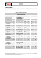
BMA250E Data sheet Page 17 The sleep time for lower-power mode 1 and 2 is set by the (0x11) sleep_dur bits as shown in the following table: Table 3: Sleep phase duration settings (0x11) sleep_dur 0000b 0001b 0010b 0011b 0100b 0101b 0110b 0111b 1000b 1001b 1010b 1011b 1100b 1101b 1110b 1111b Sleep Phase Duration tsleep 0.5ms 0.5ms 0.5ms 0.5ms 0.5ms 0.
BMA250E Data sheet Page 18 4.3 Sensor data 4.3.1 Acceleration data The width of acceleration data is 10 bits given in two´s complement representation. The 10 bits for each axis are split into an MSB upper part (one byte containing bits 9 to 2) and an LSB lower part (one byte containing bits 2 to 0 of acceleration and a (0x02, 0x04, 0x06) new_data flag). Reading the acceleration data registers shall always start with the LSB part.
BMA250E Data sheet Page 19 The BMA250E supports four different acceleration measurement ranges. A measurement range is selected by setting the (0x0F) range bits as follows: Table 5: Range selection Range 0011 0101 1000 1100 others Acceleration measurement range ±2g ±4g ±8g ±16g reserved Resolution 3.91mg/LSB 7.81mg/LSB 15.63mg/LSB 31.25mg/LSB - 4.3.2 Temperature sensor The width of temperature data is 8 bits given in two´s complement representation.
BMA250E Data sheet Page 20 4.4 Self-test This feature permits to check the sensor functionality by applying electrostatic forces to the sensor core instead of external accelerations. By actually deflecting the seismic mass, the entire signal path of the sensor can be tested.
BMA250E Data sheet Page 21 4.5 Offset compensation Offsets in measured signals can have several causes but they are always unwanted and disturbing in many cases. Therefore, the BMA250E offers an advanced set of four digital offset compensation methods which are closely matched to each other. These are slow, fast, and manual compensation as well as inline calibration. The compensation is performed with unfiltered data, and is then applied to both, unfiltered and filtered data.
BMA250E Data sheet Page 22 The public offset compensation registers (0x38) offset_x, (0x39) offset_y, (0x3A) offset_z are images of the corresponding registers in the NVM. With each image update (see section 4.6 Non-volatile memory for details) the contents of the NVM registers are written to the public registers. The public registers can be over-written by the user at any time.
BMA250E Data sheet Page 23 4.5.1 Slow compensation st Slow compensation is based on a 1 order high-pass filter, which continuously drives the average value of the output data stream of each axis to zero. The bandwidth of the high-pass filter is configured with bit (0x37) cut_off according to Table 7Fehler! Verweisquelle konnte nicht gefunden werden..
BMA250E Data sheet Page 24 Register (0x36) cal_trigger is a write-only register. Once triggered, the status of the fast correction process is reflected in the status bit (0x36) cal_rdy. Bit (0x36) cal_rdy is ‘0’ while the correction is in progress. Otherwise it is ‘1’. Bit (0x36) cal_rdy is ´0´ when (0x36) cal_trigger is not ´00´.
BMA250E Data sheet Page 25 4.6 Non-volatile memory The entire memory of the BMA250E consists of three different kinds of registers: hard-wired, volatile, and non-volatile. Part of it can be both read and written by the user. Access to nonvolatile memory is only possible through (volatile) image registers. Altogether, there are eight registers (octets) with NVM backup which are accessible by the user. The addresses of the image registers range from 0x38 to 0x3C.
BMA250E Data sheet Page 26 4.7 Interrupt controller The BMA250E is equipped with eight programmable interrupt engines. Each interrupt can be independently enabled and configured. If the trigger condition of an enabled interrupt is fulfilled, the corresponding status bit is set to ´1´ and the selected interrupt pin is activated. The BMA250E provides two interrupt pins, INT1 and INT2; interrupts can be freely mapped to any of these pins.
BMA250E Data sheet Page 27 In latched mode an asserted interrupt status and the selected pin are cleared by writing ´1´ to bit (0x21) reset_int. If the activation condition still holds when it is cleared, the interrupt status is asserted again with the next change of the acceleration registers. In the temporary mode an asserted interrupt and selected pin are cleared after a defined period of time. The behaviour of the different interrupt modes is shown graphically in figure 6.
BMA250E Data sheet Page 28 4.7.3 Electrical behaviour (INT pin# to open-drive or push-pull) Both interrupt pins can be configured to show the desired electrical behaviour. The ´active´ level of each interrupt pin is determined by the (0x20) int1_lvl and (0x20) int2_lvl bits. If (0x20) int1_lvl = ´1´ (´0´) / (0x20) int2_lvl = ´1´ (´0´), then pin “INT1” / pin “INT2” is active ´1´ (´0´).
BMA250E Data sheet Page 29 4.7.5 Slope / any-motion detection Slope / any-motion detection uses the slope between successive acceleration signals to detect changes in motion. An interrupt is generated when the slope (absolute value of acceleration difference) exceeds a preset threshold. It is cleared as soon as the slope falls below the threshold. The principle is made clear in figure 7.
BMA250E Data sheet Page 30 4.7.5.1 Enabling (disabling) for each axis Any-motion detection can be enabled (disabled) for each axis separately by writing ´1´ (´0´) to bits (0x16) slope_en_x, (0x16) slope_en_y, (0x16) slope_en_z. The criteria for any-motion detection are fulfilled and the slope interrupt is generated if the slope of any of the enabled axes exceeds the threshold (0x28) slope_th for [(0x27) slope_dur +1] consecutive times.
BMA250E Data sheet Page 31 4.7.6 Tap sensing Tap sensing has a functional similarity with a common laptop touch-pad or clicking keys of a computer mouse. A tap event is detected if a pre-defined slope of the acceleration of at least one axis is exceeded. Two different tap events are distinguished: A ‘single tap’ is a single event within a certain time, followed by a certain quiet time. A ‘double tap’ consists of a first such event followed by a second event within a defined time frame.
BMA250E Data sheet Page 32 The parameters (0x2A) tap_shock and (0x2A) tap_quiet apply to both single tap and double tap detection, while (0x2A) tap_dur applies to double tap detection only. Within the duration of (0x2A) tap_shock any slope exceeding (0x2B) tap_th after the first event is ignored. Contrary to this, within the duration of (0x2A) tap_quiet no slope exceeding (0x2B) tap_th must occur, otherwise the first event will be cancelled. 4.7.6.
BMA250E Data sheet Page 33 4.7.6.4 Axis and sign information of tap sensing The sign of the slope of the first tap which triggered the interrupt is stored in bit (0x0B) tap_sign (´0´ means positive sign, ´1´ means negative sign). The value of this bit persists after clearing the interrupt. The axis which triggered the interrupt is indicated by bits (0x0B) tap_first_x, (0x0B) tap_first_y, and (0x0B) tap_first_z. The bit corresponding to the triggering axis contains a ´1´ while the other bits hold a ´0´.
BMA250E Data sheet Page 34 4.7.7 Orientation recognition The orientation recognition feature informs on an orientation change of the sensor with respect to the gravitational field vector ‘g’. The measured acceleration vector components with respect to the gravitational field are defined as shown in figure 9.
BMA250E Data sheet Page 35 For each orientation mode the (0x0C) orient bits have a different meaning as shown in Table 14 to Table 16: Table 14: Meaning of the (0x0C) orient bits in symmetrical mode (0x0C) orient Name Angle x00 portrait upright 315° < < 45° x01 portrait upside down 135° < < 225° x10 landscape left 45° < < 135° x11 landscape right 225° < < 315° Condition |acc_y| < |acc_x| - ‘hyst’ and acc_x - ‘hyst’’ ≥ 0 |acc_y| < |acc_x| - ‘hyst’ and acc_x + ‘hyst’ < 0 |acc_y| ≥ |ac
BMA250E Data sheet Page 36 Figure 10 shows the typical switching conditions between the four different orientations for the symmetrical mode i.e. without hysteresis: portrait portraitupright upright landscape left portrait portraitupside upside down landscape landscaperight right portrait upright 2 1.5 1 0.5 0 0 45 90 135 180 225 270 315 360 -0.5 acc_y/acc_x -1 acc_x/sin(theta) -1.
BMA250E Data sheet Page 37 4.7.7.1 Orientation blocking The change of the (0x0C) orient value and – as a consequence – the generation of the interrupt can be blocked according to conditions selected by setting the value of the (0x2C) orient_blocking bits as described by Table 17. Table 17: Blocking conditions for orientation recognition (0x2C) orient_blocking 00b 01b 10b 11b Conditions no blocking theta blocking or acceleration in any axis > 1.5g theta blocking or acceleration slope in any axis > 0.
BMA250E Data sheet Page 38 device position changes in the x-y-plane while orientation changes with respect to the z-axis are ignored. A change of the orientation of the z-axis, and hence a state change of bit (0x0C) orient<2> is ignored (considered) when bit (0x2D) orient_ud_en is set to ‘0’ (‘1’). BST-BMA250E-DS004-06 | Revision 1.3 | April 2015 Bosch Sensortec © Bosch Sensortec GmbH reserves all rights even in the event of industrial property rights.
BMA250E Data sheet Page 39 4.7.8 Flat detection The flat detection feature gives information about the orientation of the devices´ z-axis relative to the g-vector, i. e. it recognizes whether the device is in a flat position or not. The flat angle is adjustable by (0x2E) flat_theta from 0° to 44.8°. The flat angle can be set according to following formula: 1 atan flat_theta 8 A hysteresis of the flat detection can be enabled by (0x2F) flat_hy bits.
BMA250E Data sheet Page 40 4.7.9 Low-g interrupt This interrupt is based on the comparison of acceleration data against a low-g threshold, which is most useful for free-fall detection. The interrupt is enabled (disabled) by writing ´1´ (´0´) to the (0x17) low_en bit. There are two modes available, ‘single’ mode and ‘sum’ mode.
BMA250E Data sheet Page 41 4.7.10 High-g interrupt This interrupt is based on the comparison of acceleration data against a high-g threshold for the detection of shock or other high-acceleration events. The high-g interrupt is enabled (disabled) per axis by writing ´1´ (´0´) to bits (0x17) high_en_x, (0x17) high_en_y, and (0x17) high_en_z, respectively. The high-g threshold is set through the (0x26) high_th register.
BMA250E Data sheet Page 42 4.7.11 No-motion / slow motion detection The slow-motion/no-motion interrupt engine can be configured in two modes. In slow-motion mode an interrupt is triggered when the measured slope of at least one enabled axis exceeds the programmable slope threshold for a programmable number of samples. Hence the engine behaves similar to the any-motion interrupt, but with a different set of parameters.
BMA250E Data sheet acceleration Page 43 acc(t0+Δt) acc(t0) slope axis x, y, or z slope(t0+Δt)= acc(t0+Δt) - acc(t0) axis x, y, or z slo_no_mot_th -slo_no_mot_th slo_no_mot_dur timer INT time Figure 11: Timing of No-motion interrupt BST-BMA250E-DS004-06 | Revision 1.3 | April 2015 Bosch Sensortec © Bosch Sensortec GmbH reserves all rights even in the event of industrial property rights. We reserve all rights of disposal such as copying and passing on to third parties.
BMA250E Data sheet Page 44 4.8 Softreset A softreset causes all user configuration settings to be overwritten with their default value and the sensor to enter normal mode. A softreset is initiated by means of writing value 0xB6 to register (0x14) softreset. Subsequently a waiting time of tw,up1 (max.) is required prior to accessing any configuration registers. BST-BMA250E-DS004-06 | Revision 1.
BMA250E Data sheet Page 45 5. FIFO Operation 5.1 FIFO Operating Modes The BMA250E features an integrated FIFO memory capable of storing up to 32 frames. Conceptually each frame consists of three 16 bit words corresponding to the x, y and z- axis, which are sampled at the same point in time. At the core of the FIFO is a buffer memory, which can be configured to operate in the following modes: FIFO Mode: In FIFO mode the acceleration data of the selected axes are stored in the buffer memory.
BMA250E Data sheet Page 46 5.2 FIFO Data Readout The FIFO stores the data that are also available at the acceleration read-out registers (0x02) to (0x07). Thus, all configuration settings apply to the FIFO data as well as the acceleration data readout registers. The FIFO read out is possible through register (0x3F). The readout can be performed using burst mode since the read address counter is no longer incremented, when it has reached address (0x3F).
BMA250E Data sheet Page 47 5.4 FIFO Interrupts The FIFO controller can generate two different interrupt events, a FIFO-full and a watermark event. The FIFO-full and watermark interrupts are functional in all FIFO operating modes. The watermark interrupt is asserted when the fill level in the buffer has reached the frame count defined by register (0x30) fifo_water_mark_trigger_retain. In order to enable (disable) the watermark interrupt, the (0x17) int_fwm_en bit must be set to ‘1’ (‘0’).
BMA250E Data sheet Page 48 6. Register description 6.1 General remarks The entire communication with the device is performed by reading from and writing to registers. Registers have a width of 8 bits; they are mapped to a common space of 64 addresses from (0x00) up to (0x3F). Within the used range there are several registers which are either completely or partially marked as ‘reserved’. Any reserved bit is ignored when it is written and no specific value is guaranteed when read.
BMA250E Data sheet Page 49 6.
BMA250E Data sheet Page 50 Register 0x00 (BGW_CHIPID) The register contains the chip identification code. Name Bit Read/Write Reset Value Content 0x00 7 R n/a Bit Read/Write Reset Value Content 3 R n/a chip_id<7:0>: BGW_CHIPID 6 R n/a 5 R n/a 4 R n/a 2 R n/a 1 R n/a 0 R n/a chip_id<7:4> chip_id<3:0> Fixed value b’1111’1001 Register 0x02 (ACCD_X_LSB) The register contains the least-significant bits of the X-channel acceleration readout value.
BMA250E Data sheet Page 51 Register 0x03 (ACCD_X_MSB) The register contains the most-significant bits of the X-channel acceleration readout value. When reading out X-channel acceleration values, data consistency is guaranteed if the ACCD_X_LSB is read out before the ACCD_X_MSB and shadow_dis=’0’. In this case, after the ACCD_X_LSB has been read, the value in the ACCD_X_MSB register is locked until the ACCD_X_MSB has been read.
BMA250E Data sheet Page 52 Register 0x04 (ACCD_Y_LSB) The register contains the least-significant bits of the Y-channel acceleration readout value. When reading out Y-channel acceleration values, data consistency is guaranteed if the ACCD_Y_LSB is read out before the ACCD_Y_MSB and shadow_dis=’0’. In this case, after the ACCD_Y_LSB has been read, the value in the ACCD_Y_MSB register is locked until the ACCD_Y_MSB has been read.
BMA250E Data sheet Page 53 Register 0x05 (ACCD_Y_MSB) The register contains the most-significant bits of the Y-channel acceleration readout value. When reading out Y-channel acceleration values, data consistency is guaranteed if the ACCD_Y_LSB is read out before the ACCD_Y_MSB and shadow_dis=’0’. In this case, after the ACCD_Y_LSB has been read, the value in the ACCD_Y_MSB register is locked until the ACCD_Y_MSB has been read.
BMA250E Data sheet Page 54 Register 0x06 (ACCD_Z_LSB) The register contains the least-significant bits of the Z-channel acceleration readout value. When reading out Z-channel acceleration values, data consistency is guaranteed if the ACCD_Z_LSB is read out before the ACCD_Z_MSB and shadow_dis=’0’. In this case, after the ACCD_Z_LSB has been read, the value in the ACCD_Z_MSB register is locked until the ACCD_Z_MSB has been read.
BMA250E Data sheet Page 55 Register 0x07 (ACCD_Z_MSB) The register contains the most-significant bits of the Z-channel acceleration readout value. When reading out Z-channel acceleration values, data consistency is guaranteed if the ACCD_Z_LSB is read out before the ACCD_Z_MSB and shadow_dis=’0’. In this case, after the ACCD_Z_LSB has been read, the value in the ACCD_Z_MSB register is locked until the ACCD_Z_MSB has been read.
BMA250E Data sheet Page 56 Register 0x08 (ACCD_TEMP) The register contains the current chip temperature represented in two’s complement format. A readout value of temp<7:0>=0x00 corresponds to a temperature of 23°C. Name Bit Read/Write Reset Value Content 0x08 7 R n/a Bit Read/Write Reset Value Content 3 R n/a temp<7:0>: ACCD_TEMP 6 R n/a 5 R n/a 4 R n/a 2 R n/a 1 R n/a 0 R n/a temp<7:4> temp<3:0> Temperature value (two s-complement format) BST-BMA250E-DS004-06 | Revision 1.
BMA250E Data sheet Page 57 Register 0x09 (INT_STATUS_0) The register contains interrupt status flags. Each flag is associated with a specific interrupt function. It is set when the associated interrupt triggers. The setting of latch_int<3:0> controls if the interrupt signal and hence the respective interrupt flag will be permanently latched, temporarily latched or not latched. The interrupt function associated with a specific status flag must be enabled.
BMA250E Data sheet Page 58 Register 0x0A (INT_STATUS_1) The register contains interrupt status flags. Each flag is associated with a specific interrupt function. It is set when the associated interrupt engine triggers. The setting of latch_int<3:0> controls if the interrupt signal and hence the respective interrupt flag will be permanently latched, temporarily latched or not latched. The interrupt function associated with a specific status flag must be enabled.
BMA250E Data sheet Page 59 Register 0x0B (INT_STATUS_2) The register contains interrupt status flags. Each flag is associated with a specific interrupt engine. It is set when the associated interrupt engine triggers. The setting of latch_int<3:0> controls if the interrupt signal and hence the respective interrupt flag will be permanently latched, temporarily latched or not latched. The interrupt function associated with a specific status flag must be enabled.
BMA250E Data sheet Page 60 Register 0x0C (INT_STATUS_3) The register contains interrupt status flags. Each flag is associated with a specific interrupt engine. It is set when the associated interrupt engine triggers. With the exception of orient<3:0> the setting of latch_int<3:0> controls if the interrupt signal and hence the respective interrupt flag will be permanently latched, temporarily latched or not latched. The interrupt function associated with a specific status flag must be enabled.
BMA250E Data sheet Page 61 Register 0x0E (FIFO_STATUS) The register contains FIFO status flags.
BMA250E Data sheet Page 62 Register 0x0F (PMU_RANGE) The register allows the selection of the accelerometer g-range.
BMA250E Data sheet Page 63 Register 0x11 (PMU_LPW) Selection of the main power modes and the low power sleep period.
BMA250E Data sheet Page 64 Register 0x12 (PMU_LOW_POWER) Configuration settings for low power mode. Name Bit Read/Write Reset Value Content 0x12 7 R/W 0 PMU_LOW_POWER 6 5 R/W R/W 0 0 4 R/W 0 reserved lowpower_mode sleeptimer_mode reserved Bit Read/Write Reset Value Content 3 R/W 0 2 R/W 0 1 R/W 0 0 R/W 0 reserved lowpower_mode: select ‘0’ LPM1, or ‘1´ LPM2 configuration for SUSPEND and LOW_POWER mode.
BMA250E Data sheet Page 65 Register 0x13 (ACCD_HBW) Acceleration data acquisition and data output format. Name Bit Read/Write Reset Value Content 0x13 7 R/W 0 data_high_bw ACCD_HBW 6 R/W 0 (1 in 8-bit mode) shadow_dis Bit Read/Write Reset Value Content 3 R/W 0 2 R/W 0 data_high_bw: shadow_dis: reserved: 5 R/W 0 4 R/W 0 reserved 1 R/W 0 0 R/W 0 reserved select whether ‘1´ unfiltered, or ‘0’ filtered data may be read from the acceleration data registers.
BMA250E Data sheet Page 66 Register 0x14 (BGW_SOFTRESET) Controls user triggered reset of the sensor. Name Bit Read/Write Reset Value Content 0x14 7 W 0 Bit Read/Write Reset Value Content 3 W 0 softreset: BGW_SOFTRESET 6 5 W W 0 0 4 W 0 2 W 0 0 W 0 softreset 1 W 0 softreset 0xB6 triggers a reset. Other values are ignored. Following a delay, all user configuration settings are overwritten with their default state or the setting stored in the NVM, wherever applicable.
BMA250E Data sheet Page 67 Register 0x17 (INT_EN_1) Controls which interrupt engines in group 1 are enabled.
BMA250E Data sheet Page 68 Register 0x18 (INT_EN_2) Controls which interrupt engines in group 2 are enabled.
BMA250E Data sheet Page 69 Register 0x19 (INT_MAP_0) Controls which interrupt signals are mapped to the INT1 pin.
BMA250E Data sheet Page 70 Register 0x1A (INT_MAP_1) Controls which interrupt signals are mapped to the INT1 and INT2 pins.
BMA250E Data sheet Page 71 Register 0x1B (INT_MAP_2) Controls which interrupt signals are mapped to the INT2 pin.
BMA250E Data sheet Page 72 Register 0x1E (INT_SRC) Contains the data source definition for interrupts with selectable data source.
BMA250E Data sheet Page 73 Register 0x20 (INT_OUT_CTRL) Contains the behavioural configuration (electrical behaviour) of the interrupt pins.
BMA250E Data sheet Page 74 Register 0x21 (INT_RST_LATCH) Contains the interrupt reset bit and the interrupt mode selection.
BMA250E Data sheet Page 75 Register 0x23 (INT_1) Contains the threshold definition for the low-g interrupt. Name Bit Read/Write Reset Value Content 0x23 7 W 0 Bit Read/Write Reset Value Content 3 R/W 0 low_th<7:0>: INT_1 6 R/W 0 5 R/W 1 4 R/W 1 2 R/W 0 1 R/W 0 0 R/W 0 low_th<7:4> low_th<3:0> low-g interrupt trigger threshold according to low_th<7:0> • 7.81 mg in a range from 0 g to 1.
BMA250E Data sheet Page 76 Register 0x25 (INT_3) Contains the delay time definition for the high-g interrupt. Name Bit Read/Write Reset Value Content 0x25 7 R/W 0 Bit Read/Write Reset Value Content 3 R/W 1 high_dur<7:0>: INT_3 6 R/W 0 5 R/W 0 4 R/W 0 2 R/W 1 1 R/W 1 0 R/W 1 high_dur<7:4> high_dur<3:0> high-g interrupt trigger delay according to [high_dur<7:0> + 1] • 2 ms in a range from 2 ms to 512 ms; the default corresponds to a delay of 32 ms.
BMA250E Data sheet Page 77 Register 0x27 (INT_5) Contains the definition of the number of samples to be evaluated for the slope interrupt (anymotion detection) and the slow/no-motion interrupt trigger delay.
BMA250E Data sheet Page 78 Register 0x28 (INT_6) Contains the threshold definition for the any-motion interrupt. Name Bit Read/Write Reset Value Content 0x28 7 R/W 0 Bit Read/Write Reset Value Content 3 R/W 0 slope_th<7:0>: INT_6 6 R/W 0 5 R/W 0 4 R/W 1 2 R/W 1 1 R/W 0 0 R/W 0 slope_th<7:4> slope_th<3:0> Threshold of the any-motion interrupt. It is range-dependent and defined as a sample-to-sample difference according to slope_th<7:0> · 3.91 mg (2-g range) / slope_th<7:0> · 7.
BMA250E Data sheet Page 79 Register 0x2A (INT_8) Contains the timing definitions for the single tap and double tap interrupts.
BMA250E Data sheet Page 80 Register 0x2B (INT_9) Contains the definition of the number of samples processed by the single / double-tap interrupt engine after wake-up in low-power mode. It also defines the threshold definition for the single and double tap interrupts.
BMA250E Data sheet Page 81 Register 0x2C (INT_A) Contains the definition of hysteresis, blocking, and mode for the orientation interrupt Name Bit Read/Write Reset Value Content 0x2C 7 R/W 0 INT_A 6 R/W 0 reserved orient_hyst<2:0> Bit Read/Write Reset Value Content 3 R/W 1 2 R/W 0 orient_blocking<1:0> 5 R/W 0 4 R/W 1 1 R/W 0 0 R/W 0 orient_mode<1:0> reserved: write ‘0’ orient_hyst<2:0>: sets the hysteresis of the orientation interrupt; 1 LSB corresponds to 62.
BMA250E Data sheet Page 82 Register 0x2D (INT_B) Contains the definition of the axis orientation, up/down masking, and the theta blocking angle for the orientation interrupt.
BMA250E Data sheet Page 83 Register 0x2F (INT_D) Contains the definition of the flat interrupt hold time and flat interrupt hysteresis.
BMA250E Data sheet Page 84 Register 0x30 (FIFO_CONFIG_0) Contains the FIFO watermark level. Name Bit Read/Write Reset Value Content 0x30 7 R/W n/a Bit Read/Write Reset Value Content 3 R/W 0 FIFO_CONFIG_0 6 R/W n/a reserved 5 R/W 0 4 R/W 0 fifo_water_mark_level_trigger_retain< 5:4> 2 R/W 0 1 R/W 0 0 R/W 0 fifo_water_mark_level_trigger_retain<3:0> reserved: write ‘0’ fifo_water_mark_level_trigger_retain<5:0>: fifo_water_mark_level_trigger_retain<5:0> defines the FIFO watermark level.
BMA250E Data sheet Page 85 Register 0x32 (PMU_SELF_TEST) Contains the settings for the sensor self-test configuration and trigger.
BMA250E Data sheet Page 86 Register 0x33 (TRIM_NVM_CTRL) Contains the control settings for the few-time programmable non-volatile memory (NVM).
BMA250E Data sheet Page 87 Register 0x34 (BGW_SPI3_WDT) Contains settings for the digital interfaces.
BMA250E Data sheet Page 88 Register 0x36 (OFC_CTRL) Contains control signals and configuration settings for the fast and the slow offset compensation.
BMA250E Data sheet Page 89 Register 0x37 (OFC_SETTING) Contains configuration settings for the fast and the slow offset compensation.
BMA250E Data sheet Page 90 Register 0x38 (OFC_OFFSET_X) Contains the offset compensation value for x-axis acceleration readout data.
BMA250E Data sheet Page 91 Register 0x39 (OFC_OFFSET_Y) Contains the offset compensation value for y-axis acceleration readout data.
BMA250E Data sheet Page 92 Register 0x3A (OFC_OFFSET_Z) Contains the offset compensation value for z-axis acceleration readout data.
BMA250E Data sheet Page 93 Register 0x3C (TRIM_GP1) Contains general purpose data register with NVM back-up. Name Bit Read/Write Reset Value Content 0x3C 7 R/W 0 Bit Read/Write Reset Value Content 3 R/W 0 GP1<7:0>: TRIM_GP1 6 R/W 0 5 R/W 0 4 R/W 0 2 R/W 0 1 R/W 0 0 R/W 0 GP1<7:4> GP1<3:0> general purpose NVM image register not linked to any sensor-specific functionality; register may be written to NVM and is restored after each power-up or softreset BST-BMA250E-DS004-06 | Revision 1.
BMA250E Data sheet Page 94 Register 0x3E (FIFO_CONFIG_1) Contains FIFO configuration settings. The FIFO buffer memory is cleared and the fifo-full flag is cleared when writing to FIFO_CONFIG_1 register.
BMA250E Data sheet Page 95 Register 0x3F (FIFO_DATA) FIFO data readout register. The format of the LSB and MSB components corresponds to that of the acceleration data readout registers. The new data flag is preserved. Read burst access may be used since the address counter will not increment when the read burst is started at the address of FIFO_DATA. The entire frame is discarded when a fame is only partially read out.
BMA250E Data sheet Page 96 7. Digital interfaces The BMA250E supports two serial digital interface protocols for communication as a slave with a host device (when operating in general mode): SPI and I²C. The active interface is selected by the state of the Pin#11 (PS) ‘protocol select’ pin: ´0´ (´1´) selects SPI (I²C). For details please refer to section 8). By default, SPI operates in the standard 4-wire configuration.
BMA250E Data sheet Page 97 7.1 Serial peripheral interface (SPI) The timing specification for SPI of the BMA250E is given in the following table: Table 22: SPI timing Parameter Clock Frequency SCK Low Pulse SCK High Pulse SDI Setup Time SDI Hold Time Condition Max Units Max. Load on SDI or SDO = 25pF, VDDIO ≥ 1.62V fSPI 10 MHz VDDIO < 1.62V 7.
BMA250E Data sheet Page 98 The following figure shows the definition of the SPI timings given in the following figure: tCSB_setup tCSB_hold CSB SCK tSCKL tSCKH SDI SDO tSDI_setup tSDI_hold tSDO_OD Figure 13: SPI timing diagram The SPI interface of the BMA250E is compatible with two modes, ´00´ and ´11´. The automatic selection between [CPOL = ´0´ and CPHA = ´0´] and [CPOL = ´1´ and CPHA = ´1´] is controlled based on the value of SCK after a falling edge of CSB.
BMA250E Data sheet Page 99 The basic write operation waveform for 4-wire configuration is depicted in figure 14. During the entire write cycle SDO remains in high- impedance state.
BMA250E Data sheet Page 100 The data bits are used as follows: Bit0: Read/Write bit. When 0, the data SDI is written into the chip. When 1, the data SDO from the chip is read. Bit1-7: Address AD(6:0). Bit8-15: when in write mode, these are the data SDI, which will be written into the address. When in read mode, these are the data SDO, which are read from the address. Multiple read operations are possible by keeping CSB low and continuing the data transfer.
BMA250E Data sheet Page 101 7.2 Inter-Integrated Circuit (I²C) The I²C bus uses SCL (= SCx pin, serial clock) and SDA (= SDx pin, serial data input and output) signal lines. Both lines are connected to VDDIO externally via pull-up resistors so that they are pulled high when the bus is free. The I²C interface of the BMA250E is compatible with the I²C Specification UM10204 Rev. 03 (19 June 2007), available at http://www.nxp.com.
BMA250E Data sheet Page 102 Figure 18 shows the definition of the I²C timings given in Table 23: SDA tBUF tf tLOW SCL tHIGH tr tHDSTA tHDDAT tSUDAT SDA tSUSTA tSUSTO Figure 18: I²C timing diagram The I²C protocol works as follows: START: Data transmission on the bus begins with a high to low transition on the SDA line while SCL is held high (start condition (S) indicated by I²C bus master). Once the START signal is transferred by the master, the bus is considered busy.
BMA250E Data sheet Page 103 I²C write access: I²C write access can be used to write a data byte in one sequence. The sequence begins with start condition generated by the master, followed by 7 bits slave address and a write bit (RW = 0). The slave sends an acknowledge bit (ACK = 0) and releases the bus. Then the master sends the one byte register address. The slave again acknowledges the transmission and waits for the 8 bits of data which shall be written to the specified register address.
BMA250E Data sheet Page 104 Example of an I²C read access: Slave Adress Start S 0 0 1 1 0 RW ACKS 0 0 0 dummy Control byte X Register adress (0x02) 0 0 0 0 0 1 ACKS 0 Data byte Slave Adress Start Sr 0 0 1 1 0 Read Data (0x02) RW ACKS 0 0 1 Data byte X X X X X X Read Data (0x03) ACKM X X X X X Data byte X … X X X X X X X X X X X X X X X X X Data byte Data byte Read Data (0x07) X X … X Read Data (0x05) ACKM Read Data (0x06) X
BMA250E Data sheet Page 105 8. Pin-out and connection diagram 8.
BMA250E Data sheet Page 106 8.2 Connection diagram 4-wire SPI Figure 24: 4-wire SPI connection Note: the recommended value for C1, C2 is 100 nF. BST-BMA250E-DS004-06 | Revision 1.3 | April 2015 Bosch Sensortec © Bosch Sensortec GmbH reserves all rights even in the event of industrial property rights. We reserve all rights of disposal such as copying and passing on to third parties. BOSCH and the symbol are registered trademarks of Robert Bosch GmbH, Germany.
BMA250E Data sheet Page 107 8.3 Connection diagram 3-wire SPI Figure 25: 3-wire SPI connection Note: the recommended value for C1, C2 is 100 nF. BST-BMA250E-DS004-06 | Revision 1.3 | April 2015 Bosch Sensortec © Bosch Sensortec GmbH reserves all rights even in the event of industrial property rights. We reserve all rights of disposal such as copying and passing on to third parties. BOSCH and the symbol are registered trademarks of Robert Bosch GmbH, Germany.
BMA250E Data sheet Page 108 8.4 Connection diagram I2C Figure 26: I²C connection Note: the recommended value for C1, C2 is 100 nF. BST-BMA250E-DS004-06 | Revision 1.3 | April 2015 Bosch Sensortec © Bosch Sensortec GmbH reserves all rights even in the event of industrial property rights. We reserve all rights of disposal such as copying and passing on to third parties. BOSCH and the symbol are registered trademarks of Robert Bosch GmbH, Germany.
BMA250E Data sheet Page 109 9. Package 9.1 Outline dimensions The sensor housing is a standard LGA package. Its dimensions are the following. Pin1 marking: Metal pad internally connected to GND (external connection not recommended) Figure 27: Package outline dimensions BST-BMA250E-DS004-06 | Revision 1.3 | April 2015 Bosch Sensortec © Bosch Sensortec GmbH reserves all rights even in the event of industrial property rights.
BMA250E Data sheet Page 110 9.2 Sensing axes orientation If the sensor is accelerated in the indicated directions, the corresponding channel will deliver a positive acceleration signal (dynamic acceleration). If the sensor is at rest and the force of gravity is acting along the indicated directions, the output of the corresponding channel will be negative (static acceleration).
BMA250E Data sheet Page 111 9.3 Landing Pattern Recommendation For the design of the landing patterns, we recommend the following dimensioning: Figure 29: Landing patterns; dimensions are in mm Same tolerances as given for the outline dimensions (Chapter 9.1, Figure 27) should be assumed. A wiring no-go area in the top layer of the PCB below the sensor is strongly recommended (e.g. no vias, wires or other metal structures). BST-BMA250E-DS004-06 | Revision 1.
BMA250E Data sheet Page 112 9.4 Marking 9.4.1 Mass production devices Table 26: Marking of mass production samples Labeling CCC TL Name Symbol Remark Lot counter CCC 3 alphanumeric digits, variable to generate mass production trace-code Product number T 1 alphanumeric digit, fixed to identify product type, T = “I” Sub-con ID L 1 alphanumeric digit, variable to identify sub-con Pin 1 identifier • -- 9.4.
BMA250E Data sheet Page 113 9.
BMA250E Data sheet Page 114 9.6 Handling instructions Micromechanical sensors are designed to sense acceleration with high accuracy even at low amplitudes and contain highly sensitive structures inside the sensor element. The MEMS sensor can tolerate mechanical shocks up to several thousand g's. However, these limits might be exceeded in conditions with extreme shock loads such as e.g. hammer blow on or next to the sensor, dropping of the sensor onto hard surfaces etc.
BMA250E Data sheet Page 115 9.7 Tape and reel specification The BMA250E is shipped in a standard cardboard box. The box dimension for 1 reel is: L x W x H = 35cm x 35cm x 6cm. BMA250E quantity: 10,000pcs per reel, please handle with care. Figure 31: Tape and reel dimensions in mm BST-BMA250E-DS004-06 | Revision 1.3 | April 2015 Bosch Sensortec © Bosch Sensortec GmbH reserves all rights even in the event of industrial property rights.
BMA250E Data sheet Page 116 9.7.1 Orientation within the reel Processing direction Figure 32: Orientation of the BMA250E devices relative to the tape BST-BMA250E-DS004-06 | Revision 1.3 | April 2015 Bosch Sensortec © Bosch Sensortec GmbH reserves all rights even in the event of industrial property rights. We reserve all rights of disposal such as copying and passing on to third parties. BOSCH and the symbol are registered trademarks of Robert Bosch GmbH, Germany.
BMA250E Data sheet Page 117 9.8 Environmental safety The BMA250E sensor meets the requirements of the EC restriction of hazardous substances (RoHS) directive, see also: Directive 2002/95/EC of the European Parliament and of the Council of 8 September 2011 on the restriction of the use of certain hazardous substances in electrical and electronic equipment. 9.8.1 Halogen content The BMA250E is halogen-free.
BMA250E Data sheet Page 118 10. Legal disclaimer 10.1 Engineering samples Engineering Samples are marked with an asterisk (*) or (e) or (E). Samples may vary from the valid technical specifications of the product series contained in this data sheet. They are therefore not intended or fit for resale to third parties or for use in end products. Their sole purpose is internal client testing. The testing of an engineering sample may in no way replace the testing of a product series.
BMA250E Data sheet Page 119 11. Document history and modification Rev. No 0.1 0.2 0.3 0.4 0.5 0.6 0.7 1.0 1.1 1.2 Chapter All 1, 4.1, 4.2, 6.2, 7.1, 9.3 4.5.2, 4.7.8, 6.2, 9.1, 9.3 1, 4.2, 4.7.3, 4.7.7, 6.2, 9.3, 9.4.1, 9.8 4.7 6.2 4.2 4.5.1 4.7.6 6.2 7.2 1.