
Datasheet

BMA250E
Data sheet
Page 97
BST-BMA250E-DS004-06 | Revision 1.3 | April 2015 Bosch Sensortec
© Bosch Sensortec GmbH reserves all rights even in the event of industrial property rights. We reserve all rights of disposal such as copying and passing on to
third parties. BOSCH and the symbol are registered trademarks of Robert Bosch GmbH, Germany.
Note: Specifications within this document are subject to change without notice.
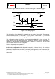
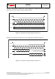
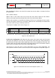
7.1 Serial peripheral interface (SPI)
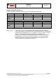
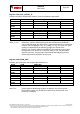
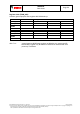
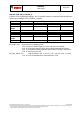
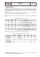
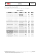
The timing specification for SPI of the BMA250E is given in the following table:
Table 22: SPI timing
Parameter
Symbol
Condition
Min
Max
Units
Clock Frequency
f
SPI
Max. Load on SDI
or SDO = 25pF,
V
DDIO
≥ 1.62V
10
MHz
V
DDIO
< 1.62V
7.5
MHz
SCK Low Pulse
t
SCKL
20
ns
SCK High Pulse
t
SCKH
20
ns
SDI Setup Time
t
SDI_setup
20
ns
SDI Hold Time
t
SDI_hold
20
ns
SDO Output Delay
t
SDO_OD
Load = 25pF,
V
DDIO
≥ 1.62V
30
ns
Load = 25pF,
V
DDIO
< 1.62V
50
ns
Load = 250pF,
V
DDIO
> 2.4V
40
ns
CSB Setup Time
t
CSB_setup
20
ns
CSB Hold Time
t
CSB_hold
40
ns
Idle time between
write accesses, normal
mode, standby mode,
low-power mode 2
t
IDLE_wacc_nm
2
µs
Idle time between
write accesses,
suspend mode, low-
power mode 1
t
IDLE_wacc_sum
450
µs