
Information


Datasheet
eCompass BMC150
Page 58
BST-BMC150-DS000-04 | Revision 1.0 | July 2014 Bosch Sensortec
© Bosch Sensortec GmbH reserves all rights even in the event of industrial property rights. We reserve all rights of disposal such as copying and passing on to
third parties. BOSCH and the symbol are registered trademarks of Robert Bosch GmbH, Germany.
Note: Specifications within this document are subject to change without notice. Not intended for publication.
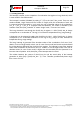
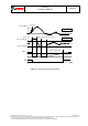
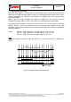
Figure 14: Interrupt latched and non-latched mode
4.9.2 Electrical behavior of magnetic interrupt pins
Both interrupt pins INT3 and DRDY are push/pull when the corresponding interrupt pin enable
bit is set, and are floating (High-Z) when the corresponding interrupt pin enable bit is disabled
(default).
4.9.3 Data ready / DRDY interrupt
This interrupt serves for synchronous reading of magnetometer data. It is generated after
storing a new set of values (DATAX, DATAY, DATAZ, RHALL) in the data registers:
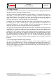
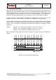
Figure 15: Data acquisition and DRDY operation (DRDY in “high active” polarity)
The interrupt mode of the Data Ready (DRDY) interrupt is fixed to non-latched.
It is enabled (disabled) by writing “1” (“0”) to “Data Ready pin En” in register 0x4E bit7.
DRDY pin polarity can be changed by the “DR polarity” bit (register 0x4E bit2), from the default
high active (“1”) to low active (“0”).
Low threshold
measurements
INT3 pin (non-latched)
INT3 pin (latched)
Readings of interrupt status register (0x4A)
Active measurement time
Preset time
Measurement Data processing
Data write into
output registers
DRDY =’1’
Measurement phase start
Data readout
Measurement
Data processing
Inactive time