
Information


BNO055
Data sheet
Page 97
BST-BNO055-DS000-14 | Revision 1.4 | June 2016 Bosch Sensortec
© Bosch Sensortec GmbH reserves all rights even in the event of industrial property rights. We reserve all rights of disposal such as copying and passing on
to third parties. BOSCH and the symbol are registered trademarks of Robert Bosch GmbH, Germany.
Note: Specifications within this document are subject to change without notice.
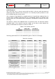
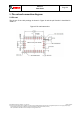
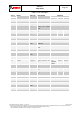
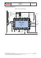
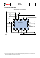
Table 5-1: Pin description
Pin #
Name
I/O Type
Description
Function
I2C
UART
HID-I2C
1
PIN1
--
Do not connect
DNC
2
GND
Ground
GND
GND
3
VDD
Supply
VDD
VDD
4
nBOOT_LOAD_PIN
Digital In
Bootloader mode
select pin (active
low)
nBOOT_LOAD_PIN
5
PS1
Digital In
Protocol select pin
1
GNDIO
VDDIO
GNDIO
6
PS0
Digital In
Protocol select pin
2
GNDIO
GNDIO
VDDIO
7
PIN7
--
Do not connect
DNC
8
PIN8
--
Do not connect
DNC
9
CAP
--
External capacitor
CAP
10
BL_IND
Digital
Out
Boot loader
indicator
DNC
11
nRESET
--
Reset pin (active
low)
nRESET
12
PIN12
--
Do not connect
DNC
13
PIN13
--
Do not connect
DNC
14
INT
Digital
Out
Interrupt output
Interrupt
15
PIN15
Ground
Connect to GNDIO
GNDIO
16
PIN16
Ground
Connect to GNDIO
GNDIO
17
COM3
Digital In
Digital interface pin
3
I2C
address
select
GNDIO
GNDIO
18
COM2
Digital I/O
Digital interface pin
2
GNDIO
19
COM1
Digital I/O
Digital interface pin
1
SCL
Rx
SCL
20
COM0
Digital I/O
Digital interface pin
0
SDA
Tx
SDA
21
PIN21
--
Do not connect
DNC
22
PIN22
--
Do not connect
DNC
23
PIN23
--
Do not connect
DNC
24
PIN24
--
Do not connect
DNC
25
GNDIO
Ground
GNDIO
GNDIO
26
XOUT32
Digital
Out
Optional OSC port
OSC Output
27
XIN32
Digital In
Optional OSC port
OSC Input
28
VDDIO
Supply
VDDIO
VDDIO