
User Manual
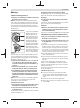
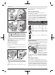
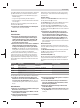
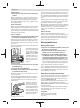

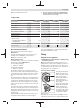
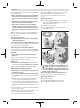
Table Of Contents
- Titelseite
- GWX 9-115/125 S
- 1
- 2 Sicherheitshinweise
- 2.1 Allgemeine Sicherheitshinweise für Elektrowerkzeuge
- 2.2 Sicherheitshinweise für Winkelschleifer
- 2.2.1 Gemeinsame Sicherheitshinweise zum Schleifen, Sandpapierscheifen, Arbeiten mit Drahtbürsten und Trennschleifen
- 2.2.2 Rückschlag und entsprechende Sicherheitshinweise
- 2.2.3 Besondere Sicherheitshinweise zum Schleifen und Trennschleifen
- 2.2.4 Weitere besondere Sicherheitshinweise zum Trennschleifen
- 2.2.5 Besondere Sicherheitshinweise zum Sandpapierschleifen
- 2.2.6 Besondere Sicherheitshinweise zum Arbeiten mit Drahtbürsten
- 2.2.7 Zusätzliche Sicherheitshinweise
- 3 Produkt- und Leistungsbeschreibung
- 4 Montage
- 5 Betrieb
- 6 Wartung und Service
- GWX 9-115/125 S
- 7
- 8 Safety instructions
- 8.1 General Power Tool Safety Warnings
- 8.2 Safety information for the angle grinder
- 8.2.1 Safety Warnings common for Grinding, Sanding, Wire Brushing or Abrasive Cutting Off operations
- 8.2.2 Kickback and Related Warnings
- 8.2.3 Safety Warnings specific for Grinding and Abrasive Cutting-Off operations
- 8.2.4 Additional Safety Warnings specific for Abrasive Cutting Off operations
- 8.2.5 Safety Warnings specific for Sanding operations
- 8.2.6 Safety Warnings specific for Wire Brushing operations
- 8.2.7 Additional safety information
- 9 Product Description and Specifications
- 10 Fitting
- 11 Operation
- 12 Maintenance and Servicing
- GWX 9-115/125 S
- 13
- 14 Consignes de sécurité
- 14.1 Avertissements de sécurité généraux pour l’outil
- 14.2 Instructions de sécurité pour meuleuses angulaires
- 14.2.1 Avertissements de sécurité communs pour les opérations de meulage, de ponçage, de brossage métallique ou de tronçonnage par meule abrasive
- 14.2.2 Rebonds et mises en garde correspondantes
- 14.2.3 Mises en garde de sécurité spécifiques aux opérations de meulage et de tronçonnage abrasif
- 14.2.4 Mises en garde de sécurité additionnelles spécifiques aux opérations de tronçonnage abrasif
- 14.2.5 Mises en garde de sécurité spécifiques aux opérations de ponçage
- 14.2.6 Mises en garde de sécurité spécifiques aux opérations de brossage métallique
- 14.2.7 Consignes de sécurité additionnelles
- 15 Description des prestations et du produit
- 16 Montage
- 17 Mise en marche
- 18 Entretien et Service après‑vente
- GWX 9-115/125 S
- 19
- 20 Indicaciones de seguridad
- 20.1 Advertencias de peligro generales para herramientas eléctricas
- 20.2 Indicaciones de seguridad para amoladoras angulares
- 20.2.1 Indicaciones de seguridad generales para el amolado, el lijado con papel de lija y los trabajos con cepillos de alambre o el tronzado
- 20.2.2 Contragolpe e indicaciones de seguridad al respecto
- 20.2.3 Indicaciones de seguridad específicas para operaciones de amolado y tronzado
- 20.2.4 Indicaciones de seguridad específicas adicionales para operaciones de tronzado
- 20.2.5 Indicaciones de seguridad específicas para el lijado con papel de lija
- 20.2.6 Indicaciones de seguridad específicas para el trabajo con cepillos de alambre
- 20.2.7 Indicaciones de seguridad adicionales
- 21 Descripción del producto y servicio
- 22 Montaje
- 23 Operación
- 24 Mantenimiento y servicio
- GWX 9-115/125 S
- 25
- 26 Instruções de segurança
- 26.1 Indicações gerais de advertência para ferramentas eléctricas
- 26.2 Instruções de segurança para rebarbadoras
- 26.2.1 Indicações de segurança comuns para operações de desbaste, de lixamento, de escovagem com arame ou de corte abrasivo
- 26.2.2 Efeito de coice e indicações relacionadas
- 26.2.3 Instruções de segurança específicas para operações de desbaste e de corte abrasivo
- 26.2.4 Indicações de segurança adicionais, específicas para operações de corte abrasivo
- 26.2.5 Indicações de segurança específicas para operações de lixamento
- 26.2.6 Indicações de segurança específicas para operações de escovagem com arame
- 26.2.7 Instruções de segurança adicionais
- 27 Descrição do produto e do serviço
- 28 Montagem
- 29 Funcionamento
- 30 Manutenção e assistência técnica
- GWX 9-115/125 S
- 31
- 32 Avvertenze di sicurezza
- 32.1 Avvertenze generali di sicurezza per elettroutensili
- 32.2 Avvertenze di sicurezza per smerigliatrici angolari
- 32.2.1 Avvertenze di sicurezza valide per operazioni di smerigliatura, levigatura, spazzolatura o taglio ad abrasione
- 32.2.2 Contraccolpi e relative avvertenze
- 32.2.3 Avvertenze di pericolo specifiche per operazioni di smerigliatura e di taglio ad abrasione
- 32.2.4 Avvertenze di sicurezza supplementari specifiche per operazioni di taglio con abrasivi
- 32.2.5 Avvertenze di sicurezza specifiche per operazioni di levigatura
- 32.2.6 Avvertenze di sicurezza specifiche per operazioni di spazzolatura
- 32.2.7 Avvertenze di sicurezza supplementari
- 33 Descrizione del prodotto e dei servizi forniti
- 34 Montaggio
- 35 Uso
- 36 Manutenzione ed assistenza
- GWX 9-115/125 S
- 37
- 38 Veiligheidsaanwijzingen
- 38.1 Algemene waarschuwingen voor elektrische gereedschappen
- 38.2 Veiligheidsaanwijzingen voor haakse slijpmachines
- 38.2.1 Algemene veiligheidsaanwijzingen voor slijpen, schuren, borstelen of doorslijpen
- 38.2.2 Terugslag en daarmee verwante waarschuwingen
- 38.2.3 Bijzondere waarschuwingen voor (door)slijpen
- 38.2.4 Extra waarschuwingen speciaal voor doorslijpen
- 38.2.5 Bijzondere waarschuwingen voor schuren
- 38.2.6 Bijzondere waarschuwingen voor werken met draadborstels
- 38.2.7 Aanvullende veiligheidsaanwijzingen
- 39 Beschrijving van product en werking
- 40 Montage
- 41 Gebruik
- 42 Onderhoud en service
- GWX 9-115/125 S
- 43
- 44 Sikkerhedsinstrukser
- 44.1 Generelle sikkerhedsinstrukser til el‑værktøj
- 44.2 Sikkerhedsinstrukser til vinkelslibere
- 44.2.1 Fælles sikkerhedsadvarsler for arbejdsopgaver, der omfatter slibning, pudsning, stålbørstning eller slibende skæring
- 44.2.2 Advarsler vedrørende tilbageslag og lignende
- 44.2.3 Sikkerhedsadvarsler specifikt for slibe- og skærearbejde
- 44.2.4 Yderligere sikkerhedsadvarsler specifikt for slibende skærearbejde
- 44.2.5 Sikkerhedsadvarsler specifikt for pudsearbejde
- 44.2.6 Sikkerhedsadvarsler specifikt for stålbørstningsarbejde
- 44.2.7 Ekstra sikkerhedsanvisninger
- 45 Produkt- og ydelsesbeskrivelse
- 46 Montering
- 47 Brug
- 48 Vedligeholdelse og service
- GWX 9-115/125 S
- 49
- 50 Säkerhetsanvisningar
- 50.1 Allmänna säkerhetsanvisningar för elverktyg
- 50.2 Säkerhetsanvisningar för vinkelslipar
- 50.2.1 Säkerhetsvarningar som är gemensamma för slipning, stålborstning eller materialnedtagning
- 50.2.2 Kast och relaterade varningar
- 50.2.3 Säkerhetsvarningar som är specifika för slipning och slipande kapningarbeten
- 50.2.4 Ytterligare säkerhetsvarningar som är specifika för slip- och skärarbete
- 50.2.5 Säkerhetsvarningar som är specifika för slipningen
- 50.2.6 Säkerhetsvarningar som är specifika för trådborstningen
- 50.2.7 Ytterligare säkerhetsanvisningar
- 51 Produkt- och prestandabeskrivning
- 52 Montage
- 53 Drift
- 54 Underhåll och service
- GWX 9-115/125 S
- 55
- 56 Sikkerhetsanvisninger
- 56.1 Generelle advarsler om elektroverktøy
- 56.2 Sikkerhetsinformasjoner for vinkelsliper
- 56.2.1 Sikkerhetsanvisninger for sliping, pussing, stålbørsting og kappesliping
- 56.2.2 Tilbakeslag og tilknyttede advarsler
- 56.2.3 Spesielle sikkerhetsregler ved slipe- og kappearbeid
- 56.2.4 Spesielle sikkerhetsregler for kappearbeid
- 56.2.5 Spesielle sikkerhetsregler for slipearbeid
- 56.2.6 Spesielle sikkerhetsregler for metallbørsting
- 56.2.7 Ekstra sikkerhetsanvisninger
- 57 Produktbeskrivelse og ytelsesspesifikasjoner
- 58 Montering
- 59 Bruk
- 60 Service og vedlikehold
- GWX 9-115/125 S
- 61
- 62 Turvallisuusohjeet
- 62.1 Sähkötyökalujen yleiset turvallisuusohjeet
- 62.2 Kulmahiomakoneen turvallisuusohjeet
- 62.2.1 Laikkahiontaa, hiomakarahiontaa, teräsharjausta ja katkaisuleikkausta koskevat yleiset turvallisuusohjeet
- 62.2.2 Takapotku ja siihen liittyvät varoitukset
- 62.2.3 Laikkahionta- ja katkaisutöitä koskevat erityiset turvallisuusohjeet
- 62.2.4 Katkaisutöitä koskevat lisäturvallisuusohjeet
- 62.2.5 Hiomatöitä koskevat turvallisuusohjeet
- 62.2.6 Teräsharjausta koskevat turvallisuusohjeet
- 62.2.7 Lisäturvallisuusohjeet
- 63 Tuotteen ja ominaisuuksien kuvaus
- 64 Asennus
- 65 Käyttö
- 66 Hoito ja huolto
- GWX 9-115/125 S
- 67
- 68 Υποδείξεις ασφαλείας
- 68.1 Γενικές υποδείξεις ασφάλειας για ηλεκτρικά εργαλεία
- 68.2 Υποδείξεις ασφαλείας για γωνιακούς λειαντήρες
- 68.2.1 Κοινές προειδοποιήσεις ασφάλειας για εργασίες λείανσης, τριψίματος, χρήσης συρματόβουρτσας ή κοπής
- 68.2.2 Ανάκρουση και σχετικές προειδοποιήσεις
- 68.2.3 Προειδοποιήσεις ασφαλείας ειδικά για εργασίες λείανσης και κοπής
- 68.2.4 Πρόσθετες προειδοποιήσεις ασφάλειας ειδικά για εργασίες κοπής
- 68.2.5 Προειδοποιήσεις ασφάλειας ειδικά για εργασίες τριψίματος
- 68.2.6 Προειδοποιήσεις ασφάλειας ειδικά για εργασίες με χρήση συρματόβουρτσας
- 68.2.7 Πρόσθετες υποδείξεις ασφάλειας
- 69 Περιγραφή προϊόντος και ισχύος
- 70 Συναρμολόγηση
- 71 Λειτουργία
- 72 Συντήρηση και σέρβις
- GWX 9-115/125 S
- 73
- 74 Güvenlik talimatı
- 74.1 Elektrikli El Aletleri İçin Genel Güvenlik Uyarıları
- 74.2 Taşlama makineleri için güvenlik talimatı
- 74.2.1 Taşlama, zımparalama, telli fırçalama ve aşındırıcı kesme işlemleri için ortak güvenlik uyarıları
- 74.2.2 Geri Tepme ve İlgili Uyarılar
- 74.2.3 Taşlama ve Aşındırıcı Kesme işlemleri için Güvenlik Uyarıları
- 74.2.4 Aşındırıcı kesme işlemleri için özel ek güvenlik uyarıları
- 74.2.5 Zımparalama işlemlerine özel güvenlik uyarıları
- 74.2.6 Telli fırçalama işlemlerine özel güvenlik uyarıları
- 74.2.7 Ek güvenlik talimatı
- 75 Ürün ve performans açıklaması
- 76 Montaj
- 77 İşletim
- 78 Bakım ve servis
- GWX 9-115/125 S
- 79
- 80 Wskazówki bezpieczeństwa
- 80.1 Ogólne zasady bezpieczeństwa podczas pracy z elektronarzędziami
- 80.2 Wskazówki dotyczące bezpieczeństwa pracy ze szlifierkami kątowymi
- 80.2.1 Wspólne zasady bezpieczeństwa pracy podczas szlifowania za pomocą tarcz oraz szlifowania za pomocą papieru ściernego, obróbki powierzchni za pomocą szczotek drucianych i cięcia za pomocą tarcz
- 80.2.2 Zjawisko odrzutu i związane z tym ostrzeżenia
- 80.2.3 Szczególne zasady bezpieczeństwa pracy podczas szlifowania i cięcia za pomocą tarcz
- 80.2.4 Dodatkowe zasady bezpieczeństwa podczas cięcia tarczą ścierną
- 80.2.5 Zasady bezpieczeństwa pracy podczas szlifowania
- 80.2.6 Zasady bezpieczeństwa podczas oczyszczania powierzchni szczotką drucianą
- 80.2.7 Dodatkowe wskazówki dotyczące bezpieczeństwa
- 81 Opis urządzenia i jego zastosowania
- 82 Montaż
- 83 Praca
- 84 Konserwacja i serwis
- GWX 9-115/125 S
- 85
- 86 Bezpečnostní upozornění
- 86.1 Všeobecná varovná upozornění pro elektrické nářadí
- 86.2 Bezpečnostní pokyny pro úhlové brusky
- 86.2.1 Bezpečnostní pokyny pro broušení, pískování, drátkování nebo brusné oddělování
- 86.2.2 Zpětný ráz a související pokyny
- 86.2.3 Bezpečnostní pokyny pro operace broušení a brusného oddělování
- 86.2.4 Doplňkové bezpečnostní pokyny pro operace abrazivního rozbrušování
- 86.2.5 Bezpečnostní pokyny pro operace broušení
- 86.2.6 Bezpečnostní pokyny pro operace drátkování
- 86.2.7 Dodatečné bezpečnostní pokyny
- 87 Popis výrobku a výkonu
- 88 Montáž
- 89 Provoz
- 90 Údržba a servis
- GWX 9-115/125 S
- 91
- 92 Bezpečnostné upozornenia
- 92.1 Všeobecné bezpečnostné výstrahy – elektrické náradie
- 92.2 Bezpečnostné pokyny pre uhlovú brúsku
- 92.2.1 Všeobecné bezpečnostné výstrahy pre obrusovanie, brúsenie, kefovanie alebo abrazívne rezanie
- 92.2.2 Spätný ráz a súvisiace výstrahy
- 92.2.3 Bezpečnostné výstrahy pre brúsenie a abrazívne rozbrusovanie
- 92.2.4 Doplnkové bezpečnostné výstrahy týkajúce sa abrazívneho rozbrusovania
- 92.2.5 Bezpečnostné výstrahy pre brúsenie
- 92.2.6 Bezpečnostné výstrahy pre prácu s drôtenými kefami
- 92.2.7 Dodatočné bezpečnostné pokyny
- 93 Opis výrobku a výkonu
- 94 Montáž
- 95 Prevádzka
- 96 Údržba a servis
- GWX 9-115/125 S
- 97
- 98 Biztonsági tájékoztató
- 98.1 Általános biztonsági előírások az elektromos kéziszerszámokhoz
- 98.2 Biztonsági előírások sarokcsiszolókhoz
- 98.2.1 Biztonsági előírások csiszoláshoz, csiszolópapírral végzett csiszoláshoz, drótkefével végzett munkákhoz vagy csiszolással végzett vágási munkákhoz
- 98.2.2 Visszarúgás és az ezzel kapcsolatos figyelmeztetések
- 98.2.3 Biztonsági előírások a csiszoláshoz és a csiszolással végzett vágási műveletekhez
- 98.2.4 Kiegészítő biztonsági előírások a csiszolással végzett vágási műveletekhez
- 98.2.5 Biztonsági előírások a csiszolópapírral történő csiszoláshoz
- 98.2.6 Biztonsági előírások a drótkefével végzett munkákhoz
- 98.2.7 Kiegészítő biztonsági előírások
- 99 A termék és a teljesítmény leírása
- 100 Összeszerelés
- 101 Üzemeltetés
- 102 Karbantartás és szerviz
- GWX 9-115/125 S
- 103 Toлько для стран Евразийского экономического союза (Таможенного союза)
- 104 Указания по технике безопасности
- 104.1 Общие указания по технике безопасности для электроинструментов
- 104.2 Указания по технике безопасности для угловых шлифмашин
- 104.2.1 Общие предупредительные указания по шлифованию, шлифованию наждачной бумагой, для работ с проволочными щетками или отрезными шлифовальными кругами
- 104.2.2 Обратный удар и соответствующие предупредительные указания
- 104.2.3 Специальные предупредительные указания по шлифованию и отрезанию
- 104.2.4 Дополнительные специальные предупредительные указания для отрезания шлифовальным кругом
- 104.2.5 Специальные предупредительные указания для шлифования наждачной бумагой
- 104.2.6 Особые предупредительные указания для работ с проволочными щетками
- 104.2.7 Дополнительные указания по технике безопасности
- 105 Описание продукта и услуг
- 106 Сборка
- 107 Работа с инструментом
- 108 Техобслуживание и сервис
- GWX 9-115/125 S
- 109
- 110 Вказівки з техніки безпеки
- 110.1 Загальні застереження для електроприладів
- 110.2 Вказівки з техніки безпеки для кутових шліфмашин
- 110.2.1 Вказівки з техніки безпеки при шліфуванні, шліфуванні наждаком, роботах з дротяними щітками та відрізанні шліфувальним кругом
- 110.2.2 Сіпання та відповідні попередження
- 110.2.3 Особливі вказівки з техніки безпеки для шліфування та відрізання
- 110.2.4 Інші особливі попередження при відрізанні шліфувальним кругом
- 110.2.5 Особливі попередження при шліфуванні наждаком
- 110.2.6 Особливі попередження при роботі з дротяними щітками
- 110.2.7 Додаткові вказівки з техніки безпеки
- 111 Опис продукту і послуг
- 112 Монтаж
- 113 Робота
- 114 Технічне обслуговування і сервіс
- GWX 9-115/125 S
- 115 Еуразия экономикалық одағына (Кеден одағына) мүше мемлекеттер аумағында қолданылады
- 116 Қауіпсіздік нұсқаулары
- 116.1 Жалпы электр құралды қауіпсіздік нұсқаулары
- 116.2 Бұрыштық тегістеу машиналарын пайдалану кезіндегі қауіпсіздік техникасы
- 116.2.1 Майдалау, ажарлау, сым қылшықпен тазалау немесе абразивті кесу әдістері үшін қауіпсіздік нұсқаулары
- 116.2.2 Қайтарым мен тиісті ескертпелер
- 116.2.3 Майдалану мен абразивті кесуге арналған қауіпсіздік нұсқаулары
- 116.2.4 Абразивті кесуге арналған қосымша қауіпсіздік нұсқаулары
- 116.2.5 Ажарлау әрекеттері үшін қауіпсіздік нұсқаулары
- 116.2.6 Сым қылшықпен тазалау әрекеттері үшін қауіпсіздік нұсқаулары
- 116.2.7 Қосымша қауіпсіздік нұсқаулықтары
- 117 Өнім және қуат сипаттамасы
- 118 Жинау
- 119 Пайдалану
- 120 Техникалық күтім және қызмет
- GWX 9-115/125 S
- 121
- 122 Instrucţiuni de siguranţă
- 122.1 Indicaţii generale de avertizare pentru scule electrice
- 122.2 Instrucţiuni de siguranţă pentru polizoare unghiulare
- 122.2.1 Instrucţiuni de siguranţă comune pentru operaţii de rectificare, şlefuire cu hârtie abrazivă, lucrul cu perii de sârmă, lustruire sau tăiere cu disc abraziv
- 122.2.2 Recul şi avertismente corespunzătoare
- 122.2.3 Avertismente specifice privind operaţiile de şlefuire şi tăiere cu disc abraziv
- 122.2.4 Avertismente suplimentare specifice pentru operaţiile de tăiere cu disc abraziv
- 122.2.5 Instrucţiuni de siguranţă specifice pentru operaţii de şlefuire cu hârtie abrazivă
- 122.2.6 Instrucţiuni de siguranţă specifice pentru lucrul cu perii de sârmă
- 122.2.7 Instrucţiuni de siguranţă suplimentare
- 123 Descrierea produsului şi a performanţelor acestuia
- 124 Montare
- 125 Funcţionare
- 126 Întreţinere şi service
- GWX 9-115/125 S
- 127
- 128 Указания за сигурност
- 128.1 Общи указания за безопасна работа
- 128.2 Указания за безопасна работа с ъглошлайфи
- 128.2.1 Общи указания за безопасност при шлифоване, шлифоване с шкурка, почистване с телени четки или абразивно рязане
- 128.2.2 Откат и начини на избягването му
- 128.2.3 Предупреждения за безопасност, специфични за дейности по шлифоване и абразивно рязане
- 128.2.4 Допълнителни указания за безопасност, специфични за абразивно рязане
- 128.2.5 Специфични указания за безопасност при шлифоване
- 128.2.6 Специфични указания за безопасност при работа с телени четки
- 128.2.7 Допълнителни указания за безопасност
- 129 Описание на продукта и дейността
- 130 Монтиране
- 131 Работа с електроинструмента
- 132 Поддържане и сервиз
- GWX 9-115/125 S
- 133
- 134 Безбедносни напомени
- 134.1 Општи предупредувања за безбедност на електрични алати
- 134.2 Безбедносни напомени за аголни брусилки
- 134.2.1 Безбедносни предупредувања за брусење, шмирглање, жичано четкање и абразивно сечење
- 134.2.2 Одбивање и поврзани предупредувања
- 134.2.3 Безбедносни предупредувања специфични за брусење и абразивно сечење
- 134.2.4 Дополнителни безбедносни предупредувања специфични за абразивно сечење
- 134.2.5 Безбедносни предупредувања специфични за шмирглање
- 134.2.6 Безбедносни предупредувања специфични за жичано четкање
- 134.2.7 Дополнителни безбедносни напомени
- 135 Опис на производот и перформансите
- 136 Монтажа
- 137 Употреба
- 138 Одржување и сервис
- GWX 9-115/125 S
- 139
- 140 Bezbednosne napomene
- 140.1 Opšta upozorenja za električne alate
- 140.2 Sigurnosna uputstva za ugaone brusilice
- 140.2.1 Standardna bezbednosna upozorenja za operacije brušenja, šmirglanja, brušenja žičanom četkom ili abrazivnog sečenja
- 140.2.2 Povratni udarac i povezana upozorenja
- 140.2.3 Posebna bezbednosna upozorenja za operacije brušenja i abrazivnog sečenja
- 140.2.4 Dodatna posebna bezbednosna upozorenja za operacije abrazivnog sečenja
- 140.2.5 Posebna bezbednosna upozorenja za operacije glačanja
- 140.2.6 Posebna bezbednosna upozorenja za operacije brušenja žičanom četkom
- 140.2.7 Dodatne sigurnosne napomene
- 141 Opis proizvoda i specifikacija
- 142 Montaža
- 143 Rad
- 144 Održavanje i servis
- GWX 9-115/125 S
- 145
- 146 Varnostna opozorila
- 146.1 Splošna varnostna navodila za električna orodja
- 146.2 Varnostna opozorila za kotne brusilnike
- 146.2.1 Varnostna opozorila za grobo in fino brušenje, ščetkanje z žično krtačo in rezanje
- 146.2.2 Opozorila glede povratnih udarcev
- 146.2.3 Posebna varnostna opozorila za grobo brušenje in rezanje
- 146.2.4 Dodatna varnostna opozorila posebej za rezanje
- 146.2.5 Posebna varnostna opozorila za postopek finega brušenja
- 146.2.6 Posebna varnostna opozorila za postopek ščetkanja z žično krtačo
- 146.2.7 Dodatna varnostna opozorila
- 147 Opis izdelka in njegovega delovanja
- 148 Montaža
- 149 Delovanje
- 150 Vzdrževanje in servisiranje
- GWX 9-115/125 S
- 151
- 152 Sigurnosne napomene
- 152.1 Opće upute za sigurnost za električne alate
- 152.2 Sigurnosne napomene za kutne brusilice
- 152.2.1 Uobičajena sigurnosna upozorenja za brušenje, brušenje brusnim papirom, brušenje žičanom četkom, poliranje i abrazivno rezanje
- 152.2.2 Povratni udar i povezana upozorenja
- 152.2.3 Posebna sigurnosna upozorenja za brušenje i abrazivno rezanje
- 152.2.4 Dodatna posebna sigurnosna upozorenja za abrazivno rezanje
- 152.2.5 Posebna sigurnosna upozorenja za brušenje brusnim papirom
- 152.2.6 Posebna sigurnosna upozorenja za brušenje čeličnom četkom
- 152.2.7 Dodatne sigurnosne napomene
- 153 Opis proizvoda i radova
- 154 Montaža
- 155 Rad
- 156 Održavanje i servisiranje
- GWX 9-115/125 S
- 157
- 158 Ohutusnõuded
- 158.1 Üldised ohutusnõuded
- 158.2 Ohutusnõuded nurklihvmasinate kasutamisel
- 158.2.1 Ühised ohutusnõuded lihvimisel, liivapaberiga lihvimisel, traatharjadega töötamisel ja lõikamisel
- 158.2.2 Tagasilöök ja asjaomased ohutusnõuded
- 158.2.3 Ohutuse erinõuded lihvimisel ja lõikamisel
- 158.2.4 Täiendavad ohutusnõuded abrasiivsete lõiketööde tegemisel
- 158.2.5 Ohutuse erinõuded lihvimisel
- 158.2.6 Ohutuse erinõuded harjamisel
- 158.2.7 Täiendavad ohutusnõuded
- 159 Toote kirjeldus ja kasutusjuhend
- 160 Paigaldus
- 161 Kasutus
- 162 Hooldus ja korrashoid
- GWX 9-115/125 S
- 163
- 164 Drošības noteikumi
- 164.1 Vispārējie drošības noteikumi darbam ar elektroinstrumentiem
- 164.2 Drošības noteikumi leņķa slīpmašīnām
- 164.2.1 Kopējie drošības noteikumi rupjajai un smalkajai slīpēšanai, apstrādei ar stiepļu suku un griešanai ar abrazīvo disku
- 164.2.2 Atsitiens un ar to saistītie norādījumi
- 164.2.3 Īpašie drošības noteikumi, veicot slīpēšanu un griešanu ar abrazīvu disku
- 164.2.4 Papildu drošības noteikumi, veicot griešanu ar abrazīvu disku
- 164.2.5 Īpašie drošības noteikumi, veicot slīpēšanu ar smilšpapīra loksni
- 164.2.6 Īpašie drošības noteikumi, veicot apstrādi ar stiepļu suku
- 164.2.7 Papildu drošības noteikumi
- 165 Izstrādājuma un tā funkciju apraksts
- 166 Montāža
- 167 Lietošana
- 168 Apkalpošana un apkope
- GWX 9-115/125 S
- 169
- 170 Saugos nuorodos
- 170.1 Bendrosios darbo su elektriniais įrankiais saugos nuorodos
- 170.2 Saugos nuorodos dirbantiems su kampinio šlifavimo mašinomis
- 170.2.1 Bendrosios įspėjamosios nuorodos atliekantiems šlifavimo, apdirbimo vieliniais šepečiais, šlifavimo naudojant šlifavimo popierių ir pjaustymo abrazyviniais pjovimo diskais darbus
- 170.2.2 Atatranka ir su ja susijusios įspėjamosios nuorodos
- 170.2.3 Specialios saugos nuorodos atliekantiems šlifavimo ir pjovimo abrazyviniais diskais darbus
- 170.2.4 Papildomos specialios saugos nuorodos atliekantiems pjovimo abrazyviniais diskais darbus
- 170.2.5 Saugos nuorodos atliekantiems šlifavimo naudojant šlifavimo popierių darbus
- 170.2.6 Saugos nuorodos atliekantiems šlifavimo vieliniais šepečiais darbus
- 170.2.7 Papildomos saugos nuorodos
- 171 Gaminio ir savybių aprašas
- 172 Montavimas
- 173 Naudojimas
- 174 Priežiūra ir servisas
- GWX 9-115/125 S
- GWX 9-115/125 S
- ١٨١
- ١٨٢ إرشادات الأمان
- ١٨٢۔١ تحذيرات أمان عامة للعدد الكهربائية
- ١٨٢۔٢ تعليمات الأمان للجلاخات الزاوية
- ١٨٢۔٢۔١ تحذيرات الأمان المشتركة لعمليات الجلخ أو السنفرة أو التنظيف بالفرشات السلكية أو القطع السحجي
- ١٨٢۔٢۔٢ الصدمة الارتدادية والتحذيرات المتعلقة بها
- ١٨٢۔٢۔٣ تحذيرات الأمان الخاصة بعمليات التجليخ والقطع السحجي
- ١٨٢۔٢۔٤ تحذيرات الأمان الخاصة بعمليات القطع السحجي
- ١٨٢۔٢۔٥ تحذيرات الأمان الخاصة بأعمال الصنفرة
- ١٨٢۔٢۔٦ تحذيرات الأمان الخاصة بأعمال الصقل بالفرشات السلكية
- ١٨٢۔٢۔٧ إرشادات الأمان الإضافية
- ١٨٣ وصف المنتج والأداء
- ١٨٤ التركيب
- ١٨٥ التشغيل
- ١٨٦ الصيانة والخدمة
- GWX 9-115/125 S
- 187
- 188 دستورات ایمنی
- 188.1 هشدارهای ایمنی عمومی برای ابزارهای برقی
- 188.2 راهنمائیها و نکات ایمنی برای دستگاه سنگ فرز
- 188.2.1 هشدارهای ایمنی مشترک برای عملیات سنگزنی، سنبادهکاری، برسکاری یا برش
- 188.2.2 پس زدن دستگاه و هشدارهای ایمنی
- 188.2.3 هشدارهای ایمنی خاص برای عملیات ساییدن و برش سایشی
- 188.2.4 سایر هشدارهای ایمنی ویژه برای عملیات برش
- 188.2.5 هشدارهای ایمنی مخصوص عملیات سنباده زنی
- 188.2.6 هشدارهای ایمنی مخصوص کار با برس سیمی
- 188.2.7 سایر راهنماییهای ایمنی
- 189 توضیحات محصول و کارکرد
- 190 نصب
- 191 طرز کار با دستگاه
- 192 مراقبت و سرویس

20 | English
ing lever (1) upward and rotate the protective guard (7) into
the required position.
u Always position the protective guard (7) such that all
three red cams on the unlocking lever (1) engage in
the corresponding openings on the protective guard
(7).
u Adjust the protective guard (7) such that sparking in
the direction of the operator is prevented.
u The protective guard (7) must only be adjustable
while the unlocking lever (1) is actuated. Otherwise,
the power tool must not be used any more under any
circumstances and must be sent to the after-sales ser-
vice.
Note: The coding cams on the protective guard (7) ensure
that only a protective guard that is suitable for the power
tool can be fitted.
Protective guard for cutting
u Always use the protective guard for cutting (9) when
cutting bonded abrasives.
u Provide sufficient dust extraction when cutting stone.
The protective guard for cutting (9) is fitted in the same way
as the protective guard for grinding (7).
Extraction guard for cutting with a guide block
The extraction guard for cutting with a guide block (18) is fit-
ted in the same way as the protective guard for grinding (7).
Side handle
u Do not operate your power tool without the side
handle (6).
Screw the side handle (6) on the left or right of the machine
head depending on how your are working.
Hand guard
u Always fit the hand guard (14) when working with the
cup brush/disc brush (15) or diamond core cutter (20).
Attach the hand guard (14) to the auxiliary handle (6).
Fitting and removing abrasive tools
u Pull the plug out of the socket before carrying out any
work on the power tool.
u Do not touch grinding and cutting discs until they have
cooled down. The discs can become very hot while work-
ing.
u Only use original X-LOCK application tools that carry the
X-LOCK logo. A maintained clamping gauge of max.
1.6mm can only be guaranteed with original X-LOCK ap-
plication tools. A higher clamping gauge can lead to insec-
ure clamping, potentially causing the clamp tool to come
loose.
u X-LOCK application tools do not need additional clamping
flanges or support flanges.
u Make sure that the application tool and the holder are not
deformed and are free from dirt and particles.
Pay attention to the dimensions of the abrasive tools.
Make sure that both X-LOCK catches are open (see figure
below) before fitting the X-LOCK application tool.
If necessary, clean the area between the two X-LOCK
catches.
Fitting the abrasive tool
Place the grinding/cutting/flap disc in a central position
on the X-LOCK holder, parallel to the bearing surface
and with the right side facing up.
Push the disc into the holder.
The disc audibly clicks into place. Do not actuate the
lever (3) when doing so.
(3)
u After fitting, check that the edge of the abrasive tool
(
) is fitted correctly, i.e. is no higher than the refer-
ence surface (
). If the edge is higher than the refer-
ence surface, either the holder must be cleaned or the
abrasive tool must not be used.
Before removing the grinding/cutting/flap disc: Make
sure that the power tool has come to a complete stop.
Removing the abrasive tool
Open the lever (3).
The grinding/cutting/flap disc will be released.
The grinding/cutting/flap disc can be removed.
1 609 92A 4FA | (21.01.2019) Bosch Power Tools