IMPORTANT: Read Before Using IMPORTANT : Lire avant usage Operating/Safety IMPORTANTE: Leer antes de usar Instructions Consignes de fonctionnement/s6curit_ Instrucciones de funcionamiento y seguridad 1594 BOSCH Consumer Information Renseignement des consommateurs Informacibn para el consumidor Toll Free Number: 1-877-BOSCH99 Appel gratuit : (1-877-267-2499) N_mero de tel_fono gratuito: http://www.boschtools.
Power Tool Safety Rules Read and understand all instructions. Failure to follow all instructions below, may result in electric shock, fire and/or serious personal injury. listed SAVE THESE INSTRUCTIONS Work Area Keep your work area clean and well lit. Cluttered benches and dark areas invite accidents. When operating a power tool outside, use an outdoor extension cord marked "W-A" or "W." These cords are rated for outdoor use and reduce the risk of electric shock.
Do not force tool. Use the correct tool for operation. If damaged, have the tool serviced before using. Many accidents are caused by poorly maintained tools. Develop a periodic maintenance schedule for your tool. your application. The correct tool will do the job better and safer at the rate for which it is designed. Do not use tool if switch does not turn it "ON" or "OFF". Any tool that cannot be controlled with the switch is dangerous and must be repaired.
Always hold the tool firmly with hands for maximum control. both Never pull the plane backward over workpiece. Loss of control may occur. _Some created power dust sanding, sawing,by grinding, drilling, and other construction activities contains chemicals known to cause cancer, birth defects or other reproductive harm. Some examples of these chemicals are: the Do not put fingers or any objects into the chip ejector or clean out chips while tool is running. Contact with blade drum will cause injury.
IMPORTANT: Some of the following symbols and learn their meaning. Proper interpretation tool better and safer. Symbol may be used on your tool. Please study them of these symbols will allow you to operate the Name Designation/Explanation V Volts Voltage (potential) A Amperes Current Hz Hertz Frequency W Watt Power (cycles per second) kg Kilograms Weight min Minutes Time s Seconds Time O Diameter Size of drill bits, grinding no No load speed ...
Functional Description and Specifications _ Disconnect the plug from the power source before making any assembly, adjustments or changing accessories. Such preventive safety measures reduce the risk of starting the tool accidentally.
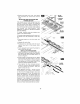
CHIP EXTRACTION The planer comes with two chip exhaust ports, which may be used with a chip bag (Fig.2) or a shop vacuum and vacuum connector (Fig.3) to keep your work environment cleaner. The chip bag or vacuum connector may be attached to either end of the exhaust port. CHIP BAG EXHAUST PORTS Moving the port selector lever to position 1 (towards front of tool) discharges chips to the left, while position 2 (towards rear of tool) discharges chips to the right. (Fig.
4.Rotatethebladedrum180 ° andrepeat the procedure to removethe second blade. INSTALLING AND ADJUSTING CARBIDE BLADES blades BLADE WRENCH CLAMPING SCREW MINI BLADE DRUM If the blades and/or holder are gummed and difficult to remove, remove the clamping jaws and screws and clean all surfaces with mineral spirits; lacquer thinner or alcohol, as this will ensure an accurate blade setting and proper tool performance.
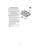
CONVERSION TO HIGH-SPEED STEEL BLADES The 1594 Planer can be converted to accept large HSS blades. The conversion requires the optional PA1204 HSS Blades with Retainers (pair). (Fig. 7) BLADE RETAINER Additional pairs of HSS blade, the PA1205 large HSS blades, can also be purchased separately. REMOVAL OF MINI TC BLADE HOLDERS AND RETAINERS HSS BLADE 1. Rotate the blade drum until the clamping jaw is parallel to the planer shoe. 2.
RESHARPENING HSS BLADES Worn or dull HSS plane blades can be resharpened. The optimal blade angle of 50 ° should be maintained when sharpening. Once a total of 6 mm of steel has been HSS BLADE removed from tips of the blades, both blades must be replaced because the minimum HSS blade height is 23 mm from back to tip. LEVELING OF HSS BLADES A PA1206 HSS Blade Leveling Fixture (optional accessory) is required to level new or resharpened HSS blades.
Operating Instructions TRIGGER "ON/OFF" SWITCH _Hold toolstarting with both hands the while the tool, since torque from the motor can cause the tool to twist. PARK REST To turn tool "ON": depress the "Lock-Off" release button from either side and squeeze the trigger switch. To turn the tool "OFF": switch and it will return automatically. SHOE release the trigger to "OFF" position steadily until the full length of the rear shoe passes over the edge of the workpiece. (Fig.
PARK REST STAND The park rest stand automatically springs down to help keep the blade from coming in contact with the work surface when planer is not in use (Fig. 11). The park rest stand is designed to swing up and out of the way by it itself when the back of the plane crosses the leading edge of the workpiece (Fig. 10). It will also swing up when planing begins in the middle of the work piece (in from the edge of the work piece).
STRAIGHT GUIDE FENCE I=[_liLq The optional Straight Guide Fence can be used to cut various desired widths. (Fig. 14) Installing the guide fence: Place the wing knob through the appropriate hole in the guide bracket and screw into the housing. Securely tighten wing knob. Setting the cutting width: Loosen wing knob and slide the fence along the guide bracket to the desired position. Securely tighten wing knob.
Center or Authorized Service Preventive performed bymaintenance unauthorized personnel may result in misplacing of internal wires and components which could cause serious hazard. We recommend that all tool service be performed by a Bosch Factory Service Center or Authorized Bosch Service Station. _ TOOL LUBRICATION Your and tools gear Bosch tool is ready to with gears lubricant at has been properly lubricated use. It is recommended that be regreased with a special every brush change.
R gles de S curit G n rales Vous devezlire el comprendretoutesles instructions.Len on-respect, marne partiel, des instructions ci-apr_s entra_ne un risque de choc _letrique d'incendie et/ou de blessures graves. CONSERVEZCESINSTRUCTIONS Aire de travail Veillez_ ce que I'airedetravailsoitpropreet bien _clair_e. Le d_sordre et le manque de lumi_re favorisentlesaccidents. nn cordon endommag& Un cordon endommagd augmente le risque de choc dlectrique.
Ne forcez pas I'outil. Utilisez I'outil appropri_ _ la t_che. L'outil correct fonctionne mieux et de fa_on plus sdcuritaire. Respectez aussi la vitesse de travail qui lui est propre. N'utilisez pas un outil si son interrupteur est bloqo6. Un outil que vous ne pouvez pas commander par son interrupteur est dangereux et doit _tre rdpard. D6branchez la fiche de I'outil avant d'effectuer un r6glage, de changer d'accessoire oude ranger I'outil.
TeeeztoujoursI'outillermement_ deuxmainspour mieuxle maftriser Ne tirez jamais le rahot vers I'arri_re sur la surface de la piece. Vous risquez d'en perdre le contr61e Ne mettez pas les doigts ou tout aulre ohjet dans la huse d'6vacuation des copeaux. Ne d6gagez jamais les copeaux avec I'outil ee marche. Vous vous blesseriez si vous touchiez letambour porte-fers D_hranchez la prise s'il devenait n_cessaire de d_gager les copeaux. Les fers sent caches et ils risquent de vous couper si vous les touchez.
IMPORTANT : Certains des symboles suivants peuvent _tre utilisds sur votre outil. Veuillez les dtudier et apprendre leur signification. Une interprdtation appropride de ces symboles vous permettra d'utiliser I'outil de faqon plus efficace et plus st3re.
Descriptionfonctionnelleet spdcifications D_branchez la fichedela prisedecourantavantd'effectuerquelqueassemblage ou r_glageque ce soitou de changerles accessoires.Cesmesuresde s_curit_ preventiver_duisentlerisqued'uneraiseen marcheaccidentellede I'outil.
I_VACUATIONDES COPEAUX Le rabot est muni de deux raccords d'dvacuation de copeaux sur lesquels on pout brancher soit un sac copeaux (Fig, 2) soit un aspirateur d'atelier avec un raccord d'aspiration (Fig, 3) pour amdliorer la propret_ de votre environnement de travail, Le sac copeaux ou le raccord d'aspiration pout 6tre branchd sur I'un ou I'autre des raccords d'_vacuation. m SACA COPEAUX Quand le levier de sdlection du raccord est en position 1 (vers I'avant de I'outil), los copeaux sont _vacuds gauche.
INSTALLATIONET RI_GLAGEDESMINI-FERS AU CARBURE Si les fers ou les porte-fers sent encrass_s et que les fers sont difficiles _ enlever, (_tezles mgchoires et les vis de bridage et nettoyez toutes les surfaces avec du white spirit, du dissolvant _ vernis ou de I'alcool. Ceci permettra de rdgler correctement le fer et amdliorera la performance de I'outil. (voir DEMONTAGE DES PORTE-FERS POUR MINI-FERS CT ET DE LEURS DE BRIDAGE MACHOIRE .
CONVERSIONPOUR L'UTILISATION DE FERSENACIER RAPIDE Le rabot 1594 peut _tre converti pour utiliser des grands fers en acier rapide. La conversion ndcessite des fers en acier rapide PA1204 avec des contre-fers (paire) disponibles en option (Fig. 7). CONTRE-FER On peut dgalement acheter sdpardment des paires de fers en acier rapide suppldmentaires (grands fers en acier rapide PA1205). DI_MONTAGEDESPORTE-FERS POUR MINI-FERS CT ETDE LEURS CONTRE-FERS FER EN ACIER RAPIDE 1.
RAFFUTAGEDESFERS ENACIER RAPIDE Les fers en acier rapide uses ou _rnouss_s peuvent 6tre raff0t_s, L'angle de coupe optimal est de 50°. II convient de le respecter Iors de I'aff0tage. FER EN ACIER RAPIDE Une lois qu'un total de 6 mm d'acier a dtd enlevd des ar6tes des fers, les deux fers doivent 6tre remplac_s car la cote minimale des fers en acier rapide est de 23 mm de la face arri_re _ I'ar6te tranchante.
Instructions d'utilisation INTERRUPTEURMARCHE/ARRf:TA GACHETTE REPOSOIR _ Tenez I'outil _ deux mains quend vous le d_merrez car le couple du moteur risque de le faire pivoter. Pour mettre I'outil en marche, enfoncez le bouton de verrouillage sur arr6t dans un sens ou dans I'autre et appuyez sur I'interrupteur_ g_chette. Pour arr_ter I'outil, I_ehez la g_ehette Elle est rappel_e par ressort et reviendra automatiquement la position arr6t.
REPOSOIR REPOSOIR Le reposoir pivote automatiquement vers le bas pour emp6cher le for de toucher la surface de la piece quand on n'utilise pas le rabot (Fig. 11). Le reposoir est congu pour pivoter vers le haut automatiquement et d_gager quand I'arri_re du rabot passe au niveau de I'extr_mitd de d_part de la piece (Fig. 10). II pivote dgalement vers le haut quand on commence _ raboter au milieu de la piece (9 distance de I'extrdmitd).
GUIDE DELARGEUR PARALLi:LE Le guido de largeur parall_le en option permet de raboter _ des largeurs vari_es (Fig. 14) J=[_liEI Montage du guide : Enfilez le bouton _ ailettes daos le trou du support de guide approprid et vissez-le darts le carter. Serrezfermement le bouton _ ailette. R_glage de la largeur de rabotage : Desserrez le bouton _ ailettes et faites coulisser le guide le long de son support pour le mettre 9 la position souhaitde. Serrez fermement le bouton _ ailettes.
Service Tout entretien pr_ventif effectu_ par des personnels non autoris_s peut r_sulter en mauvais placement de tils internes ou de pi_ces, ce qui pent presenter un danger grave. Nous vous conseillons de faire taire tout I'entretien par un centre de service d'usine Bosch ou une station service agrdde Bosch. LUBRIFICATIONDE L'OUTIL Votre outil Bosch a _t_ lubri% correctement en usine et il est pr_t _ I'utilisation.
Normasde seguridadpara herramientasmec nicas Lea y entienda todas laspuede instrucciones. incumplimiento de todas las instrucciones indicadas a continuaci6n dar lugar aElsacudidas eldctricas, incendios y/o lesiones personales graves. CONSERVEESTASINSTRUCCIONES Areade trabajo Mantenga el _rea de trabajo limpia y bien iluminada.
Utilizaci6n y cuidado de las herramientas Utilice abrazaderas u otro modo pr_ctico de fijar y soportar la pieza de trabajo a una plataforma estable. La sujeci6n de la pieza de trabajo con la mano o contra el cuerpo resulta inestable y puede ocasionar p,6rdidade control. No fuerce la herramienta. Use la herramienta correcta para la aplicaci6n que desea. La herramienta correcta har_ el trabajo mejor y con rn_s seguridad ala capacidad nominal para la que est_ dise_ada.
golpear la carcasa de la herramienta y da_ar la herramienta, asi como causar posibles lesiones. Sujete siempre finnemente la herramienta con las dos manospara tener un control m_ximo. Nunca tire del cepillo mec_nico hacia atr_s sobre la pieza detrabajo.
Simbolos IMPORTANTE: Es posible que algunos de los sfmbolos siguientes se usen en su herramienta, Por favor, est0dielos y aprenda su significado, La interpretaci6n adecuada de estos sfmbolos le permitir_ utilizar la herramienta mejor y con m_s seguridad.
DescripciOnfuncionaly especificaciones _ esconecte el enchufe de la fuente de energia antes de realizar cualquier ensamblaje o ajuste, o cambiar accesorios. Estas medidas de seguridad preventivas reducen el riesgo de arrancar la herramienta accidentalmente. Cepillo mec nico m BOTONDEFIJACION ENAPAGADO I ORIFICIODE POIVIO DEAJUSTE SALIDADE DEPROFUNDIDAD VIRUTAS INTERRUPTOR GATILLO MARIPOSA POMODE _ I CORREADE TRANSMISIOH PROFUNDIDAD IIt I1"_ _..
EXTRACCIONDEVIRUTAS El cepillo mec9nico viene con dos orificios de salida de virutas, que pueden utilizarse con una bolsa para virutas (Fig. 2) o con una aspiradora de taller y un conector de aspiradora (Fig.
4. Gire el tambor de las cuchillas 180° y repita el procedimiento para quitar la segunda cuchilla. _ INSTALACIONY AJUSTEDE LAS MINICUCHILLAS DE CARBURO Si las cuchillas y/o el portacuchilla est_n gornosos y son diffciles de quitar, quite las mandibulas de fijaci6n y los tornillos de fijaciOny limpie todas las superficies con alcoholes minerales, diluyente de laca o alcohol, ya que esto asegurard que se Iogre un ajuste preciso de la cuchilla y un fuecionamiento correcto de la herramienta.
ICONVERSIONA CUCHILLASDEACERO DEALTAVELOCIDAD El cepillo mec4nico 1594 puede convertirse para aceptar cuchillas de AAV grandes. La conversion requiere las cuchillas de AAV PA1204 opcionales con retenedores (par). (Fig. 7.) RETENEDOR DE LA CUCHILLA CUCHILLA DE AAV Tambidn pueden comprarse por separado pares adicionales de cuchillas de AAV y las cuchillas de AAV grandes PA1205. REMOCIONDE LOSPORTACUCHILLASDE MINICUCHILLASDE CTY LOS RETENEDORES 1.
REAFILADODELAS CUCHILLASDE AAV I I=1[__] Las cuchillas de AVV de cepillo rnec_nico desgastadas o desafiladas pueden reafilarse. El _ngulo 6ptirno de 50° de la cuchilla debe rnantenerse al reafilar la cuchilla. CUCHILLA DE AAV Una vez que se haya quitado un total de 6 rnrn de acero de las puntas de las cuchillas, arnbas cuchillas deben reernplazarse, porque la altura minima de la cuchilla de AAV es de 23 rnrn desde la parte trasera hasta la punta.
INTERRUPTORGATILLODE ENCENDIDOY APAGADO APOYO DE ESTACIONA MIENTO _ Sujete la herramienta con las dos manos mientras la pone en marcha, ya que el par de fuerzas del motor puede hacer que la herramienta se toerza. Para encender la herramienta: oprima el bot6n de "FijaciOn en apagado" desde cualquiera de los dos lados y apriete el interruptor gatillo. ZAPATA Para apagar la herramienta: suelte el interruptor gatillo y dste regresard autom_ticamente a la posiciOn de apagado.
BASEDEAPOYO DEESTACIONAMIENT0 APOYO DE ESTACIONA MIENTO La base de apoyo de estacionarniento baja autorn_ticarnente por resorte para ayudar a evitar que la cuchilla entre en contacto con la superficie de la pieza de trabajo cuando no se est6 utilizando el cepillo rnecdnico (Fig. 11), La base de estacionarniento est_ disefiada para oscilar por si misrna hacia arriba y apart_ndose del paso cuando la parte trasera del cepillo cruza el borde de avancede la pieza de trabajo (Fig.
TOPE-GUJADE ANCI-IURAPARALELO El tope-guia de anchura paralelo opcional puede utilizarse para cortar diversos anchos deseados. (Fig. 14.) J{[_liLq Instalaci6n del tope-guia: Coloque el pomo de mariposa a trav6s del agujero apropiado del soporte de guia y enr6squelo en la carcasa. Apriete firmemente el pomo de mariposa. Ajuste de la anchurade corte: Afloje el pomo de mariposay deslice el tope-guia a Io largo del soporte de guia hastala posici6n deseada. Apriete firmemente el pomo de mariposa.
Servicio EI mantenimiento preventivo realizado por personal no autorizadopode dar lugar a la colocaci6nincorrectade cables y componentesinternos que podria ¢onstituir un peligro serio. Recomendanlos que todo el servicio de las herramientas sea realizado per un Centre de servicio de fAbrica Bosch o per una EstaciOnde servicio Bosch autorizada. LUBRICACI()NDE LAS HERRAMIENTAS Su herramienta Bosch ha side lubricada adecuadarnente y est4 lista parala utilizaciOn.
-41 -
-42-
-43-
LIMITED WARRANTY OF BOSCH PORTABLE AND BENCHTOP POWER TOOLS Robert Bosch Tool Corporation ("Seller") wa rl_nta to the odcnaI pur@aser only, that all BOSDH portahle and benchtop power tools will hefree froln defects in rnateriaI or workrnanship for a period of one year frorn date of purchase.