
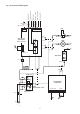
Technical data

Technical Helpline.
Note: READ THIS SECTION FULLY BEFORE COMMENCING
INSTALLATION.
12.1 General
The appliance is only suitable for fitting to a sealed system.
The flue must be installed as specified in BS5440:1.
Check that the appliance is suitable for the local conditions. i.e. gas
supply.
12.2 Unpacking
Remove the appliance from its packaging and check the contents
against the packing list.
12.3 Site Preparation
Check the correct position for the appliance has been chosen.
Refer to Section 4 and Table 8.
Check that the wall is flat and and will support the weight of the
appliance. Refer to Table 4.
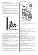
12.4 Fixing Holes ad Flue Opening
Hold the template against the wall.
Check that the template is level.
Mark the position of the fixing holes and the flue opening. Refer to Fig. 14 and 15.
Mark the centre-lines of the pipe connections to aid the pre-
plumbing of the system pipework.
Check the position of the fixing points and the flue opening before
drilling the fixing holes 60mm deep for the No.12 size plugs and
cutting the flue duct hole at 110mm diameter (150mm diameter for
internally fitted flues.
12.5 Wall Mounting Plate and Manifold
Fit the plugs and fix the top support to the wall. Refer to Fig. 14.
Check the top support is properly aligned before tightening the screws.
12.6 Gas and Water Pipes
Remove the gas cock and fix the appropriate fitting to connect the
inlet pipe and re-fit.
Pre-plumbing is not recommended if no movement in the pipes is available.
If it is necessary for the pipes to run up the back of the appliance
then they must be arranged to pass behind the expansion vessel.
Pipework must not run horizontally within the limits of the casing.
It is important that the pipes are not fixed near the appliance using
clips that put a strain on the connections.
Before the appliance is fitted to the wall thoroughly
flush the system and mains water supply.
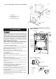
12.7 Install the Boiler
Remove the cabinet by releasing the sides and lifting from the top
location.
Check that the gas and water valves are closed.
Lift the appliance to the wall, engage in the top support. Fix and
tighten the bottom screws. Refer to Fig. 14.
Tighten the gas and water connections.
Fit a discharge pipe to the relief valve leading it away from any
electrics or where it might be a hazard.
The pipe must not be less than 15mm in diameter and must run
continuously downward outside the appliance. Refer to Fig. 6.
12. Installing The Appliance
13
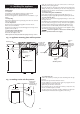
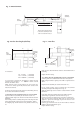
Fig. 14. Appliance mounting plate and flue position.
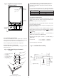
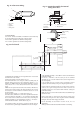
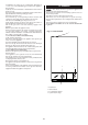
Fig. 15. Marking out the side flue position.
Mounting wall
Rear flue hole
110mm dia.
(150mm dia. for
internal fixing)
Side flue hole
110mm dia.
(150mm dia. for
internal fixing)
Appliance
casing
Mounting
plate
Fixing holes
(alternatives)
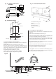
Mounting wall
Mounting
plate
222mm
Side wall
166mm
740mm
400mm
Rear flue position
Side flue position
60mm
Appliance
casing
Side flue
hole
110mm dia.
(150mm dia.
for internal
fixing)
Mounting wall
Side wall
222mm
166mm