iMPORTANT: IMPORTANT'. Read Before Using Life avant usage IMPORTANTE: Leer antes de usar Operating/Safety instructions Consignes de fonctionnernent/s_curit_ Instrucciones de funcionarniento y seguridad 3912 Consumer Information Renseignernent des consornrnateurs Inforrnaci6n Toll Free Number: 1=877=BOSCH99 For English See page 2 para el consurnidor Appel gratuit (1 =877=267=2499) : N_rnero de tel_fono http://www.boschtools.corn.
Safety r !_v*vl'-_z'l_ll_[e]l "READ ALL INSTRUCTIONS" -- Failure to follow the SAFETY RULES identified by BULLET (I) symbol listed BELOW and other safety precautions, may result in serious personal injury. General Safety Rules For Bench Top Tools Do not abuse the cord. Never use the cord to carry the tools or pull the plug from an outlet. Keep cord away from heat, oil, sharp edges or moving parts. Replace damaged cords immediately. Damaged cords increase the risk of electric shock.
Safety r !_v*vl'-_'l_ll_[e]l "READ ALL INSTRUCTIONS" -- Failure to follow the SAFETY RULES identified by BULLET (I) symbol listed BELOW and other safety precautions, may result in serious personal injury. ToolUse and Care Safety Rules for Miter Saws Use clamps or other practical way to secure and support the workpiece to a stable platform. Holding the work by hand or against your body is unstable. It allows for work to shift, causes binding of the tool and loss of control.
Safety ! r!_v*vl'-1_'l_ll_[ttl "READ ALL INSTRUCTIONS" -- Failure to follow the SAFETY RULES identified by BULLET (I) symbol listed BELOW and other safety precautions, may result in serious personal injury. Cut only one workpiece at a time. Multiple workpieces cannot be adequately clamped or braced and may bind on the blade or shift during cutting. switch. Wait for all moving parts to stop and unplug the miter saw, then work to free the jammed material.
Safety IV !_Wl'-_'l_ll_[ctl "READ ALL INSTRUCTIONS" - Failure to follow the SAFETY RULES identified by BULLET (I) symbol listed BELOW and other safety precautions, may result in serious personal injury. • Do not aBow famBiarity gained from frequent use of your miter saw to become commonplace. a careless fraction of a second is sufficient to inflict severe injury.
Safety r !_v*vl'-_'l_ll_[ttl "READ ALL INSTRUCTIONS" -- Failure to follow the SAFETY RULES identified by BULLET (I) symbol listed BELOW and other safety precautions, may result in serious personal injury. DoubleInsulated Tools Extension Cords Double insulation _ is a design concept used in electric power tools which eliminates the need for the three wire grounded power cord and grounded power supply system.
Electrical Requirements 1. Connect this saw to a 120V, 15-amp branch circuit with a 15-amp time delay fuse or circuit breaker. Using the wrong size fuse can damage the motor. r!'vAV'-_i_ll_[el When electrical power is lost due to blown fuse or other causes, the motor will gradually slow down and the braking action is initiated ONLY by the release of the trigger switch. 2. Fuses may "blow" or circuit breakers may trip frequently if motor is overloaded.
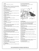
3 4 2 1 27 26 25 23 24 37 30 22 \ \ 21 10 13 14 16 20 17 10 15 18 I To avoid injury from accidental starting, remove plug from power source outlet before making any adjustments. 4. Switch Handle This handle contains the switch. The blade is lowered into the workpiece by pushing/pulling down on the handle. 1, Carrying Handle This handle is built into the head assembly for transportation. 5. Power Switch The power switch energizes the unit. 2.
7. Blade Use only 12" blades with 1" arbor hole. 26. Lower Guard Actuation Link Allows for smooth movement of the lower guard. 8. Fence Supports the workpiece. The fence has a cast in scale to make repetitive cuts easy. The fence also has holes which are used to secure an auxiliary fence if desired. 27. Upper Blade Guard Covers upper portion of the blade. 9. Kerf insert Minimizes workpiece tear-out. © 10.
S curit _ LISEZ TOUTESLES INSTRUCTIONS_ -- L'utilisateur qui n6gligerait de suivre los CONSIGNESDE SECURITE pr6c6d@sd'un point noir (I) ci-dessous et de prendre d'autres pr6cautions616mentairesrisquerait de subir de graves blessures. Consignesg6n rales de s curit pourlosoutiisd' tabli • N'abusez pas du cordon.N'utiJisez jamais Jecordonpourtranspoder Jesoutilset ne tirez pas Jafiche d'une prise. Tenez Je cordon_ I'_cad de JachaJeur,de J'huiJe,des armiesvives o, des pi_ces mobiles.
S curit _ LISEZ TOUTESLES INSTRUCTIONS_ -- L'utilisateur qui n6gligerait de suivre los CONSIGNESDE SECURITE pr6c6d6esd'un point noir (I) ci-dessous et de prendre d'autres pr6cautions616mentairesrisquerait de subir de graves blessures. Utilisation et entretiende I'ouiil • Utilisez des pincesou autre fagon pratiqued'assujettir el de supporterrouvrage _ une plate-formestable. Tenir I'ouvrageb, la main ou centre son corps n'assure pas la stabilit6 voulue.
S curit _ LISEZ TOUTESLES INSTRUCTIONS_ -- L'utilisateur qui n6gligerait de suivre les CONSIGNESDE SECURITE pr6c6d6esd'un point noir (I) ci-dessous et de prendre d'autres pr6cautions616mentairesrisquerait de subir de graves blessures. • N'introduisez pas I'ouvtage darts la lame et ne coupez d'aucurie mani_re _ ,, main libre ,,. L'ouvrage dolt _tre fixe et cramponn_o, serr_ par votre main. La scie dolt _,treins6r6e_, travers i'ouvrage doucementet _,unevitesse qui ne surchargera pas le moteur de lascie.
S curit <_LISEZ TOUTES LES INSTRUCTIONS >_-- L'utilisateur qui n6gligerait de suivre les CONSIGNES DE SECURITE pr6c6d6es d'un point noir (I) ci-dessous et de prendre d'autres pr6cautions 616mentaires risquerait de subir de graves blessures. • Ne laissez pas la familiatit_ tir_e d',ne utilisationfr_q,ente de votrescie _ onglet att_nuer vetre vigilance. N'oubliez jamaisqu'une fraction de seconded'insouciancesuffit b.causer des biessuresgraves. • PENSEZEN TERMESDE SECURITE.
S curit _ LISEZ TOUTESLES INSTRUCTIONS_ -- L'utilisateur qui n6gligerait de suivre les CONSIGNESDE SECURITE pr6c6d6esd'un point noir (I) ci-dessous et de prendre d'autres pr6cautions616mentairesrisquerait de subir de graves blessures. Doubleisolation Ralionges La doubJeisolation L_ est utilis6e dans les outils 61ectriquespour 61iminerle besoin de cordon d'alimentation avec prise de terre et de dispositif d'alimentation b,prise de terre.
Specifications 1. Branchezcette scie surun circuit de d@ivationde 120 V, 15 A avec disjoncteur ou fusible b,action diff6r6e de 15 A. L'utilisation du mauvaistype de fusible peutabfmer le moteur. 2. Les fusibies peuvent sauter ou les disjoncteurs peuvent se d6clencher souvent si le moteur est surcharg6. II peuty avoir surcharge si vous introduisez la lame dans I'ouvrage trop rapidement ou si vous mettezen marche et b,I'arr_,ttrop souvent dansun p@iodebr_ve. 3.
FarnHiarisez-vous avec votre scie onglet 3 4 2 1 27 26 25 23 24 37 30 22 \ \ 21 10 13 14 20 16 1: 10 15 18 Pour @iter les blessures r6sultant d'une raise en marche accidentelle, d6branchez lafiche de la prise de courant avant d'effectuer quelquer6ghge quece soit. pour actionner I'interrupteur g6n@al. 4. Poign_e-interrupteur Cette poign@ contient i'interrupteur. La lame est abaiss@ dans I'ouvrageen poussant/tirantla poign@vers le bas. 1.
7. Lame Utilisez uniquement des lames de 12 po avec un trou d'arbre de 1 po. 25. D_flecteur de copeaux Ce dGflecteur emp#,che les gros copeaux de pGnGtrerdans le protecteursupGrieur. 8. Guide Supporte I'ouvrage. Le guide poss_de une 6chelle graduGeincorporGepour faciliter les coupes b,rGpGtition. Le guide comporte 6galementdes trous qui serventb,fixer un guideauxiliaire,si dGsir& 26. Raccordd'actionnement du protecteurinf_rieur Permetun mouvementen douceur du protecteur infGrieur. 27.
Seguridad "LEA TODASLAS INSTRUCCIONES". El incumplimientode las NORMASDE SEGURIDADidentificadasper elsimbolo del PUNTO NEGRO(I) que se indican A CONTINUACIONy otras precaucionesde seguridad puede dar lugar a lesiones personalesgraves. Normasgeneralesde seguridadpara herramientasparatablero de banco • No abuse del cord6n. Nunca use el cord6n para JJevarlas herramientas ni tire de _J para desconectaflo del tomacorriente.
Seguridad "LEA TODASLAS INSTRUCCIONES". El incumplimientode las NORMASDE SEGURIDADidentificadasper elsimbolo del PUNTO NEGRO(I) que se indican A CONTINUACIONy otras precaucionesde seguridad puede dar lugar a lesiones personalesgraves. Utiiizaci6ny cuidadode las herramientas • Utilice abrazaderasu otto mode prdctico de fijar y soporiar Ja pieza de trabajo en una plataformaestabJe. La sujeci6n de la piezade trabajocon lamane o contrael cuerpo resulta inestable.
Seguridad "LEA TODASLAS INSTRUCCIONES". El incumplimientode las NORMASDE SEGURIDADidentificadasper elsimbolo del PUNTO NEGRO(I) que se indican A CONTINUACIONy otras precaucionesde seguridad puede dar lugar a lesiones personalesgraves. • No use la sierra hastaque se hayan retiradede la mesatedas las hetramientas,desecbes de madeta, etc., excepte la pieza de ttabajo.
Seguridad "LEA TODAS LAS INSTRUCCIONES". El incumplimiento de las NORMAS DE SEGURIDAD identificadas per el simbolo del PUNTO NEGRO (I) que se indican A CONTINUACION y otras precauciones de seguridad puede dar lugar a lesiones personalesgraves. • No permitaque la familiafizaci6n ehtenida per el use frecuente de Jasierra para cottaringJetesse vueJvaaJgehabitual. Recuerdesiempre que un descuido de unafracci6n de segundoes suficientepara causar unalesi6n grave.
Seguridad "LEA TODASLAS INSTRUCCIONES". El incumplimientode las NORMASDE SEGURIDADidentificadasper elsimbolo del PUNTO NEGRO(I) que se indican A CONTINUACIONy otras precaucionesde seguridad puede dar lugar a lesiones personalesgraves.
Requisitos . ei ctricos Conecteesta sierra a un circuito derivado de 120 V y 15 A con cortacircuito o un fusible de 15 amperios de acci6n retardada.La utilizaci6n de un fusible de tama_o incorrecto puede da_ar el motor. 2. Los fusibles puedenfundirse o los cortacircuitos pueden dispararse frecuentementesi se sobrecarga el motor. La sobrecarga puede producirse si se hace avanzar la hoja por la pieza de trabajo demasiador_,pidoo si se arranca y se detienedemasiado frecuenteen un periodo de tiempo corto.
Farniliarizaci6n con la sierra para cortar ingletes 3 2 4 1 27 26 25 23 24 37 30 22 \ 21 o 10 13 14 16 20 17 10 15 18 Para evitar lesionesdebidas a un arranque accidental, saque el enchufe del tomacorfiente de lafuente de energiaantesde hacer cualquierajuste. 4. Mango coninterrupter Este mango contiene el interrupter. La hoja se baja hacia la pieza de trabajo empujando/tirandohacia abajosobre ei mango. 1.
7. Hoja Use solamente hojas de 12" con agujero para eje portaherramienta de 1". 25. Deflectorde virutas Este deflector evita que las virutas grandes entren en el protector superior. 8. Tope-guia Soporta la piezade trabajo. El tope-guia tiene una escalafundida para hacer cortes repetitivosfAcilmente.El tope-guiatambi6ntiene agujeros que seusan parafijar un tope-guia auxiliarsi asi se desea. 26. Eslah6nde accionamiento deJprotectorinferior Permite un movimiento suavedel protector inferior. 27.
Assembly Tools Needed For Assembly And Alignment Phillips Screwdriver Combination Combination Square Square Must be True Draw Light Line on Board Straight Edge of Board 3/4" Thick Along this Edge This Edge Must be Straight Perfectly _ ?_ Should be no Gap or Overlap when Square is Flipped Over in Dotted Position ! rr'_'A'l'-'1_i_ll_t:_ Disconnect Blade Wrench (supplied) Hex "L" Wrench (supplied) 6mm Ir ¢ plug from power source before performing any assembly, adjustment or repair to avoid
Eresamblaje Herramientas necesariasparael ensamblajey ia alineaci6n Destornillador Phillips LJavedetuercaparala hoja (s.rninistrada) Llavehexagonal en "L" de 6 rnm(s.rninistrada) Laesc.adrade cornbinaci6n debeestar alineada Esc.adradecornbinaci6n Trace.ha linealigera sobrela tabiaa Jo Jargodeeste horde \ Borderecto delatabla de3/4"degrosor. Estehordedebeset recto perfectarnente _, _._ J NodebehaberespacioJibreni superposici6n[ c.andosed_ la vueltaa la esc.adrasobre la posici6nrnarcadacon.
Assembly J Unpacking and Checking Contents r !_[°,]p'i_.lln/[°]_m Before moving the saw: Lock the miter lock knob in 45 ° left or right position. Lock bevel lock handle. Lock head assembly in the down position. Never carry the tool by the cord or head assembly power switch handle. Damage to insulation could cause an electric shock. Damage to wire connections could cause a fire. Model 3912 Compound one box. Miter Saw is shipped complete in 1.
Assemblage Ensarnblaje OuverturedeI'emballageet v6rification ducontenu Desempaquetado y comprobaci6n dei contenido Avant de d6placer la scie : bloquez le bouton de blocage de I'onglet b,la position gauche ou droite 45 ° . Bloquez la poign6e de blocage de biseau. Bloquezlat_,teb,la positionabaiss6e. Antes de mover la sierra: Fije el pomo de fijaci6n de ingleteen la posici6n de 45° a la derecha o a la izquierda. Fije el mango de fijaci6n de bisel. Fije el ensamblajedel cabezalen laposici6n haciaabajo.
Assembly Removal and Installation of the Blade I I I I I r !-v&vl'-_`i_ll_[ell Disconnect plug from power source before performing any assembly, adjustment or repair to avoid possible injury. \ \ Note: Clean blade of any excess oil before installation. 1. Rotate the lower guard 1 by hand. Loosen, but do not remove, the cover plate screw 2 using a Phillips or straight screwdriver (Figure 2). 2. Rotate the cover plate 3 counterclockwise bolt 4 is exposed (Figure 2). 3. Press and hold the arbor lock.
Assemblage Ensarnblaje Instalaci6ny remoci6ndeia hoja Poseet d posedeia lame D6branchezla fiche de la prise de courant avant d'effectuer tout assemblage, r6glage ou r@arationpour @iterd'@entuellesblessures. Desconecte el enchufe de la fuente de energia antes de realizar cualquier ensamblaje,ajusteo reparaci6nparaevitar posibleslesiones. Remarque: Enleveztout exc6dentd'huile sur lalameavant lapose. NOTA: Limpie todo el exceso de aceite de la hoja antes de la instalaci6n. 1. 2. 3.
Assembly | Assembling Dust Elbow and Dust Bag 2 1. With the miter arm locked in the down position, push the dust elbow 1 onto the dust nozzle over the tabs (Figure 5). 2. The dust bag 2 attaches to the dust chute elbow 1 and is used to collect sawdust. The dust elbow can also be attached to a standard 1-1/4" vacuum tube for dust collection. 3. Position dust elbow/bag so that it does not interfere with the tool during the cutting operation for all miter/bevel settings. 4.
Assemblage Ensarnblaje Assemblageducoudede poussi reet dusac poussi re Ensamblajedeicodoparapoivoy ia boisaparapoivo 1. Le bras d'onglet 6tant bloqu6 en position descendue,poussez le coude de poussi_re 1 sur la buse b, poussi_re par-dessus les languettes(Figure5). 1. Con el brazode ingletefijado en la posici6nhacia abajo,empujeel codo para polvo 1 encima de la boquilla para polvo sobre las leng@tas (Figura5). 2.
Adjustments | 3 Disconnect plug from power source before performing any assembly, adjustment or repair to avoid possible injury. \ NOTE: Your compound miter saw was completely adjusted at the factory. However, during shipment, slight misalignment may have occurred. Check the following settings and adjust if necessary prior to using this compound miter saw. Blade Square to Table (90 °) 1. Rotate table 1 to 0° position and lock in place. 2. Lower the blade 2 and engage the lock pin 3.
R glages Ajustes Desconecte el enchufe de la fuente de gia antes de realizar cualquier ensamblaje, ajuste o reparaci6n pare evitar posibles lesiones. D6branchezla fiche de la prise de courant avant d'effectuer tout assemblage,r6glage ou r@arationpour @iterd'@entuellesblessures. REMARQUE: Votre scie b,onglet compos@ a 6t6 enti_rementr6gl@ b, Fusine.Cependant,un 16gerd6salignementpeuts'_tre produit en cours d'exp6dition.
Adjustments | Blade 45 ° To The Table 1. Rotate table 1 to 0° position and lock in place. 2. Move sliding fence to its proper position. Fence on page 54.) 3. Lower head assembly. Lock in place. 4. Loosen bevel lock handle and tilt the head assembly to 45 ° bevel. Check the 45 ° bevel stop. The bevel indicator should be on the 45 ° mark, the 45 ° bevel stop should be in full contact with the 45 ° bevel stop screw, and the blade 2 should contact the full length of the combination square 3 (Figure 9).
R glages Ajustes Lame 45° parrapport ia table 1. Gire la mesa1 hasta laposici6n de 0° y fijela en su sitio. 1. Tournezlatable 1 b,laposition 0° et bloquezen place. 2. Mueva el tope-guia deslizante hasta su posici6n apropiada. (Ver Topes-guiadeslizantesen la p_,gina55.) 2. D6placezleguide _ glissi_reb,sa position appropri6e.(Voir Guide b,glissi_re_ la page55.) 3. Bajeel ensamblajedel cabezal.Fijelo en su sitio. 3. AbaissezlatSte. Bloquezen place. 4. 4.
Adjustments Blade Square to Fence Lower the head assembly and push in the lock pin to lock in the lower position. Make sure table is in 0° detent and tighten miter lock knob. Place a combination square 1 against the fence 2 and next to the blade 3 as illustrated. Locate the square properly so it does not contact the tooth of saw blade. The saw blade should contact the full length of the square (Figure 11). 2. If blade does not contact alignment procedure. the square, follow the fence FenceAlignment a.
R glages Ajustes Lamed' querreparrapport a. guide Hojaen nguio rectoconel tope-guia 1. Abaissez la t#,teet enfoncezla cheville de blocage pour bloquer en position abaiss@. Assurez-vous que la table est au cran d'arr#,t 0° et serrez le bouton de blocage d'onglet. Phcez une @uerre b,combinaison 1 contre le guide2 et b,c6t_ de la lame3, comme illustr6. PlacezI'@uerre ad@uatement de mani_re b,ce qu'elle ne viennepas en contactavec lesdents de la lamede scie.
Miter Scale and Vernier Scale Usage The Vernier miter scale can help you adjust the miter to any 1/4 ° increment (Figure 13). / _'_ _ _' !--I_ F_I _ I I _, Vernier Miter / Indicator 40-1/4 ° The 1/4° Vernier mark (first line to right of center indicator) is over the 41° scale mark Z_T h e ce n ttii i_i _cii_'_sdir_ct _IY Miter Scale ThZ_e 1/2° 40-3/4 ° 40-1/2 ° Vernier mark is over the 42 ° scale mark The 3/4 ° Vernier mark is over the_ 43 ° scale mark Figure 13.
Usode la escala de ingletesy la escala Vernier La escala de ingletesVernier puede ayudarle a ajustar el ingleteen cualquier incrementode 1/4 ° (Figura 13). Indicadorde inglete Vernier /-- te El indicador central est_,directamente o sobre la marca de la escala a 40° \ \ \ . .
Adjustments Miter Scale (Vernier) indicator Adjustment 1. Raise the head assembly to the full-up position. 2. Through the slot 1 in the kerf insert, loosen the Phillips screw 2 that holds the indicator 3 in place (Figure 14). 3. Position the indicator 3 to align with the 0° miter mark 4. Tighten the screw 2. Crown Molding Detent Adjustment (Bevel} position. 3 1. Move sliding fence to proper Fence on page 54.) (See Sliding 2.
R glages Ajustes R6glagede i'indicateur dei'6chelle gradu6ed'onglel(Vernier) 1. LevezlatSte jusqu'&saposition enti_rementlev@. 2. Par le biais de lafente 1 pratiqu@ dans I'insert d'encoche, desserrez la vis b,empreinte cruciforme 2 qui tient I'indicateur3 en place (Figure14). 3. Ajusle dei indicador(Vernier}de ia escalade ingleles . Positionnez I'indicateur 3 de mani_re b, ce qu'il s'aligne sur la marque d'onglet 0° 4. Serrezlavis 2. 2.
Pour 6viter les blessures caus6es par un mouvement inattendu de la scie, observez To avoid injury from unexpected saw movement observe the following: les mesuressuivantes: • Unplug electric cord. Before transporting the saw, rotate head assembly to 45 ° miter, lock into detent and lock the head assembly in the lowered position. • D6branchez le cordon 61ectrique.Avant de transporter la scie, tournez la t_te b, I'onglet 45°, bloquez dans le cran d'arr#,t et bloquez lat_teen position abaiss6e.
Instalaci6n Para evitar lesiones debidas a un moviinesperado de la sierra, siga las instruccionessiguientes: • Desenchufeelcord6n el6ctrico.Antesde transportar la sierra,gire el ensamblajedel cabezalhasta el ingletede 45°, fijelo en el ret_n y fije elensamblajedel cabezalen la posici6nbajada. • Para evitar lesionesen la espalda,sujete la herramientacerca del cuerpo cuandola levante.Doble las rodillas para poderlevantarla herramienta haciendofuerza con las piernas, no con la espalda.
Installation Mounting Applications Workbench Mount the saw using either the four bolt holes (7/16") 1 or the four nail holes 2 to the workbench. Check for clearance to the left and right of the saw (Figure 16). 1. Each of the four mounting holes should be bolted securely using 7/16" flat head screws, lock washers, and hex nuts (not included). 2. Locate and mark where the saw is to be mounted. 3. Drill four (4) 7/16" diameter holes through workbench. 4.
Applications demontage Aplicaciones demontaje Etab/i Bancode trabajo Montezla scieb_1'6tablib_I'aidedes quatretrous de boulon (7/16 pc) 1 ou des quatre trous de clou 2. Assurez-vous d'un d6gagement suffisantb,gaucheet b,droite de lascie (Figure16). Monte la sierra en el banco de trabajo usandolos cuatro agujerospara pernos (7/16") 1 o los cuatro agujeros para clavos 2. Compruebeque hayaespaciolibre a la izquierday a la derechade lasierra (Figura16). 1.
Basic Saw Operations Body and Hand Position iVV_ v&v.,_.=.=,,==_== ii. ll-J_il_rPli Position your body and hands properly to make cutting easier and safer. Observe the following instructions (Figure 19). • Never place hands near cutting area. Keep hands outside the "No Hands Zone". The "No Hands Zone" is defined as the area between marked lines on the left and right side of the Base, including the entire Table and portion of the Fence within these marked lines.
Op ralions de base de la scie Operaciones basicas de la suerra Positiondu corpsel des mains Posici6ndei cuerpoy de iasmanes Positionnezvotre corps et vos mains ad6luatement pour rendre la coupe plus facile et plus sire. Observezlesinstructions suivantes(Figure19). • • Posicione el cuerpo y las manes de mode para hacer que las operaciones de corte sean mD, s fD,ciles y seguras. Siga las instrucciones siguientes (Figura19). Ne pJacezjamais Jes mains _ proximit_ de I'aite de coupe.
Basic Saw Operations Workpiece Support 3 Long workpieces have a tendency to tip over unless clamped down and properly supported from underneath. Clamps Quick Action Clamp - This clamp easily secures a workpiece in any of six (6) clamp holes around the saw (Figure 21). • Insert clamp post into clamp hole 1. • Adjust screw rod 2 to proper height, if necessary. • Press down on lever 3 to tighten clamp. • Move the head assembly to check clearance with clamp. • Pull up on lever to release clamp.
Operations de base de la scie Operaciones basicas de la suerra Supportdei'ouvrage Soportedeia piezadetrabajo Les ouvrages longs ont tendance b,basculer b.moins qu'ils ne soient cramponn6s et ne soient dQmentsupport_s par en-dessous. Las piezas de trabajo largastienen tendencia a inclinarsea menos que est6n sujetas con abrazaderasy soportadasadecuadamentedesde debajo.
Basic Saw Operations Pipe Extension Kit with Workpiece Support/Stop - This attachment 1 (accessory #80162) allows extra support for the longer workpieces (Figure 24). The stops help assist in repetitive cuts. This combines with any length 1/2" Black Pipe 2. Refer to the accessory instruction sheet for details. See page 74 for a complete accessory list. 1 (#80162) / Auxiliary Fence - Certain types of molding need a fence face extension because of the size and position of the workpiece.
Op ralions de base de la scie Operaciones basicas de la suerra H_cessairede rallonge de tuya. avec supporl/but_ed'ouvrage -Getaccessoire1 (No. 80162) offre un support suppl6mentairepour les ouvrages plus longs (Figure 24). Les but6es facilitent les coupes D, r6p6tition. Get accessoire peut #,treajout_ D,toute Iongueur de tuyau noir 2 de 1/2 po. Pour plus de d6tails, reportez-vousD,la feuille d'instructions sur lesaccessoires.Voir la listecomplete des accessoiresD, la page74.
Basic Saw Operations Detent Override ... ToEngage: 0 1. Lift the miter detent trigger 1 (Figure 27). 2. Push the detent override clip 2 forward and latch in place over edge. Release miter detent trigger 1. 3. Move miter arm 3 to any position on the miter scale. 4. Lock the miter lock knob 4 to retain miter position. 4 ToDisengage: 5. Loosen miter lock knob 4 and lift the miter detent trigger 1 to release the detent override clip 2. Sliding Base/Fence Extension _'vl :_VAV.
Operations de base de la scie Operaciones basicas de la suerra Sobrecontroidei ret n CourFcircuitage d. crand'arr t Pourengager" Para acoplarlo: 1. Soulevezla gb,chette du cran d'arr#,td'onglet 1 (Figure27). 1. Subael gatillo del ret_nde inglete1 (Figura27). 2. Poussezla pince de court-circuitagedu cran d'arr#,t2 vers I'avant et verrouillezen place par-dessusle bord. Relb, chez lagb,chettedu cran d'arr#,td'onglet 1. 2.
Saw Operations Miter Cut A miter cut is made at 0° bevel and any miter angle in the range from 52 ° left to 52 ° right. o The miter scale is cast-in on the base for easy reading. o Positive detents have been provided for fast and accurate mitering at 0°, 15°, 22.5 °, and 45 ° left and right. • There is also a crown molding detent at 31.6 ° (see Cutting Crown Molding for more information page 65).
Operations de la scie Operaciones suerra de la Coupe i'onglet • Une coupe b, I'ongletest pratiqu6eau biseau 0° et b,tout angle d'onglet variant entre52° b,gaucheet 52° b,droite. • L'6chellegradu6ed'onglet est coul6edans latable pour faciliter la lecture. • Des crans d'arr_,tpositifs ont 6t6 cr66s b,0°, 15°, 22,5° et 45° b, gaucheet &droite en vue d'une coupe rapideet exacte.
Saw Operations Bevel Cut A bevel cut is made at 0° miter and any bevel angle in the range of -3 ° to 50 ° . • There are two (2) factory set bevel stops at 0° and 45 °. (See Adjustment section if adjustments are required.) • The cast in bevel scale faces the operator reading. 5 for easy There is a positive crown molding stop at 33.9 ° . Disengage this stop unless using. (See cutting Crown Molding for details.
Operations de la scie Operaciones suerra de la Coupeenbisea. Corteenbisei Une coupe en biseauest pratiqu6eb,onglet de 0° et b,tout angle de biseauvariant entre-3 et 50°. Uncorte en bisel se hacea un inglete de 0° y cualquier_ngulo de biselen el intervalode -3° a 50°. • II existe bon hombre de but6es de biseaur6gl6esen usine b,0° et 45°. (Voir sectionR6glagesi des ajustementssont n6cessaires.) • L'6chelle gradu6e de biseau moul6e est dirig6e vers I'op6rateur pour faciliter lalecture.
Saw Operations Compound 5 Cuts A compound cut is a cut requiring both a miter setting and a bevel setting. Because it may take several tries to obtain the desired compound angle, perform test cuts on scrap material before making your cut. 3 Follow these instructionsfor makingyour compound cut: 1. Move sliding fence to proper Fence on page 54). position 1 (see Sliding 2. Extend the sliding base 2 (see Sliding Base Extension on page 54). Select the desired miter and bevel angles 3 (Figure 32).
Operations de la scie Operaciones suerra de la Coupescompos6es • Une coupe compos@ est une coupe n6cessitant un r6glage d'onglet aussi bien qu'un r6glagede biseau. • Etant donn6 qu'il faudra peut-_tre plusieurs essais pour obtenir I'angle compos6 d6sir6, effectuez des coupes d'essai sur des mat@iauxde rebutavantde pratiquervotre coupe. Cortescompuestos Suivez ces instructions pourpratiquer votre coupe compos_e " 1. D@lacez le guide b, glissi_re b, la position appropri@ 1.
Saw Operations Base Molding Base molding can be cut vertical against fence or flat on the table, BASE MOLDING • Follow the table for helpful hints on cutting base molding.
Operations de la scie IVloulures debase • Les moulures de base peuvent#,trecoup@s b,la verticalecontre le guideou b,plat sur latable. • Reportez-vous au tableau contenant des conseils utiles sur la coupe de moulures de base.
Operaciones de la sierra IVloidura de base • La moldura de basese puedecortar vertical contrael tope-guia u horizontalsobre lamesa. • Siga el cuadro para obtener consejos _tiles sobre el corte de moldura de base.
Saw Operations Cutting Crown Molding o Crown molding must be cut exactly to fit properly. o There are two ways to cut crown molding: flat on table or angled to table and fence. • Your miter saw has special miter detents of 31.6 ° left and right and a bevel detent of 33.9 ° for cutting crown molding flat on the table. • 52 ° between the back of the molding and the top flat surface that fits against the wall. 38 ° between the back of the molding and the bottom flat surface that fits against the wall.
Saw Operations Crown Molding LayingFlat on Table 33.9 ° Bevel Follow these instructions for cutting crown molding: 1. Move sliding fence to proper position (see Sliding Fence on page 54). 2. Set the bevel and miter angles using Chart 1 below. Tighten the miter lock knob and the bevel lock handle (Figure 33). 3. Crown Molding Position molding on saw table. Use the chart below for correct position. Clamp workpiece in place using the workpiece clamp.
Operations de la scie Moulures en couronne reposant _ plat sur la table | Suivezcesinstructions pourcouperJesmouJures encouronne" 1. DGplacezle guideb,glissi_reb,la position appropriGe(voir Guideb, glissi_reb,lapage55.) 2. RGglezles angles de biseau et d'onglet b,raide du Tableau 1 ciapr_s. Serrez le bouton de blocage d'onglet et la poignGede blocagede biseau(Figure33). 3. Positionnezla moulure sur la table. Reportez-vousau tableau ciapr_s pour connaftre la position correcte.
de la sierra Operaciones Moldura de techocolocada horizonta/mente sobre la mesa Bisel de 33.9 ° Sigaestasinstrucciones paracortarrnoidura detecho: 1. Mueva el tope-guia deslizante a la posici6n apropiada 1 (Vet Tope-guiadeslizanteen lap_,gina55.) 2. Ajuste los _,ngulosde bisel y de inglete usando el Cuadro 1 que aparece m_,sabajo. Apfiete el pomo de fijaci6n de inglete y el mango defijaci6n de bisel (Figura33). 3. Posicione la moldura sobre la mesa de la sierra.
Saw Operations Crown Molding Angled to Table and Fence The advantage to cutting in this position is that no bevel setting is required. Cutting is done with 45 ° miter angle. Sliding Fence Crown molding of up to 6-5/8" maximum width can be cut on your saw. Follow these instructions for cutting crown moldingangled to table and fence. 1. Position the molding so the bottom (part which is installed against the wall) is against the fence.
Operations de la scie IVioulure encouronne_ angle parrapport_ ia table et au guide • La coupe en cette position est avantageuse parce qu'aucun r6glage de biseau n'est n6cessaire.La coupe est pratiqu6eavec un angled'onglet de 45°. • Une moulure en couronne d'une largeurallant jusqu'b,6-5/8 pc peut #,trecoup6esur votre scie. Monlnre en conronne_ angle contre le guide Fixation droite d'onglet posse Suivezces instructionspourcouperlesmoulures en couronne_ anglepar rapport _ la table et au guide" 1.
Operaciones de la sierra Moiduradetechoen_ngulorespecto a ia mesay al tope-guia • La ventajade cortar en esta posici6n es que no se requiereajuste de bisel.El corte se hacecon el _,ngulode ingletede 45°. • Con la sierra se puede cortar moldura de techo de hasta una anchura maximade 6-5/8". Molduradetecho en _ngulocontrael tope-guia Aditamentode ingleterecto instalado Siga estas instrucciones para cortar moldumde techo en dngulo respecto a la mesaif al tope-guia. 1.
Saw Operations Special Cuts 4 Cutting bowed material and round material are only examples of special cuts. CuttingBowedMateria/ 3 IV !'vAvl'-_r'_ll_[el If workpiece 1 is bowed or warped, clamp it 2 with the outside bowed face toward the fence 3. Always make certain that there is no gap between the workpiece, fence and table along the line of cut 4. Bent or warped workpieces can twist or rock and may cause binding on the spinning saw blade while cutting (Figure 35). \ \ Cutting Roundor Irregularly Sh
Operations de la scie Operaciones suerra de la Coupessp6ciales Cortesespeciales La coupe de mat6riaux courb_s et de mat6riaux rends ne constitue qu'un exemplede coupes sp6ciales. Los cortes de materialarqueadoy de materialredondo son solamente ejemplos de cortes especiales. Coupe de mat_riauxcourb_s Corte de materia/ arqueado Si I'ouvrage 1 est courb6 ou gondol6, cramponnez-le 2 avec la face courb_e ext6rieuredirig6e vers le guide 3.
Accessories Pipe Extension (BB1202) Kit with Work A ccessoires Piece/Support Stop N_cessaire de rallonge de tuyau avec support/butte d'ouvrage (BB1202) This attachment allows extra support for the longer work pieces cut in the shop. The stops help assist in repetitive cuts. Combines with any length 1/2" Black Pipe. Cetaccessoireoffre un support suppl6mentairepour les ouvragesplus longs coup6s b, I'atelier. Les but6es facilitent les coupes b,r6p6tition.
Accesorios Juego de extensi6n de tubos con tope de soporte para la pieza de trabajo (BB1202) Este aditamento proporciona un soporte adicional para las piezasde trabajo m_,slargas que se cortan en el taller. Los topes ayudanen los cortes repetitivos. Se combina con tubo negro de 1/2" de cualquier Iongitud. Varias hojas de punta de carburo de 12" Se ofrece una amplia gama de hojas de diversos materiales, configuraciones de dientes e inclinaciones para proporcionar la hoja correcta para diversasaplicaciones.
Maintenance Lubrication and Service Preventive maintenance performed by unauthorized personnel may result in misplacing of internal wires and components which could cause serious hazard. We recommend that all tool service be performed by a Bosch Factory Service Center or Authorized Bosch Service Station. Carbon Brushes The brushes and commutator in your tool have been engineered for many hours of dependable service.
Mantenirniento lubricaci6n Rernplacernent des balais de rnoteur y Servicio Entretien El mantenimiento preventivo realizadopor personal no autorizado pude dar lugar a la colocaci6n incorrecta de cables y componentes internos que podda constituir un peligro serio. Recomendamosquetodo el servicio de las herramientassea realizadopor un Centro de servicio de f_,bricaBosch o por una Estaci6nde servicio Boschautorizada.
Nettoyage Cleaning --'------"----It "v_v&vn''-l[i_ll_iell To avoid accidents always disconnect the tool from the power supply before cleaning or performing any maintenance. The tool may be cleaned most effectively with compressed dry air. Always wear safety goggles when cleaning tools with compressed air. Pour 6viter le risque d'accidents, d6branchez toujours I'outil de la prise de courant avant de proc6derau nettoyageou b.I'entretien.
Limpieza Para evitar accidentes desconecte siempre la herramienta de la fuente de energia antes de la limpieza o de la realizaci6nde cualquier mantenimiento. La herramienta se puede limpiar m_,seficazmente con aire comprimido seco. Use gafas de seguridad siemprequelimpie herramientascon aire comprimido. Las aberturas de ventihci6n y las palancasde interruptor debenmantenerse limpias y libres de materiasextra,as. No intente limpiar introduciendoobjetos puntiagudosatrav6s de lasaberturas.
Troubleshooting Guide Duide i lectrique Electrical PROBLEM BRAKE DOES NOT STOP BLADE WiTHiN SECONDS CAUSE 1. Brushes not seated or lightly sticking. 2. Motor overheated from use of not recommended accessory or rapid on/off cycling. 3. Blade bolt loose. 4. Other SOLUTION 1. Inspect/clean or replace brushes (see Maintenance Section). 2. Use a recommended blade. Let saw cool down. PROBLJ:IViE LE FREIN N'ARRETEPASLA LAIViEBANSUN BELAI DE5 SECONDES. 5 CAUSE 1.
Guia de Localizaci6n y reparaci6n de averias Ei6ctricas PROBLEMA EL FRENO NO DETIENE LA HOJAAL CABO DE 5 SEGUNDOS. CAUSA 1. Escobillasno asentadaso quese peganligeramente. 2. Motor recalentadodebido al uso de un accesoriono recomendado o a rApidos ciclos de encendido/apagado. 3. Pernode lahoja flojo. 4. Otra. MEDIDADE CORRECCION 1. Inspeccione/limpie las escobillas (vea la secci6n Mantenimiento). 2. Useuna hoja recomendada. Dejeque lasierra se enfrie. 3. Aprieteei pernode lahoja. 4. Servicioautorizado.
Generalites General PROBLEM CAUSE 2. Pivot spring or guard spring properly after service. 3. Sawdust accumulation. SOLUTION PROBLEM CAUSE PROBLi:ME HEAD ASSEMBLY WiLL NOT FULL RiSE OR BLADE GUARD WiLL NOT FULLY CLOSE. 1. Part failure. not replaced 1. Authorized service. 2. Authorized service. 3. Clean head assembly. BLADE BINDS, JAMS, ROUGH CUTS. CAUSE BURNS 1. Ddaillance de pi_ces. 2. Le ressort de pivot ou le ressort de protecteur n'a pas 6t6 remis en place adGquatement apr_s I'entretien. 3.
Guia de Localizaci6n y reparaci6n de averias Generales PROBLEMA ELENSAMBLAJE DELCABEZALTAMBALEA. CAUSA 1. Puntos de pivote sueltos. MEDIDADE CORRECCION 1. VeaAjuste dei pivotede bisel en la secci6nAjustes. PROBLEIViA EL ENSAMBLAJE DEL CABEZAL NO SUBE COIVlPLETAMENTE0 EL PROTECTOR DE LA HOJANO SE CIERRACOIViPLETAIViENTE. CAUSA 1. Fallode pieza. 2. Resorte del pivote o resorte del protector no colocado adecuadamentedespu6s del servicio de ajustesy reparaciones. 3. Acumulaci6nde serfin.
LIMIITEDWARRANTYOFBOSCHPORTABLEANDBENCHTOPPOWERTOOLS S-B Power Tool Company ("Seller") warrants to the original purchaser only, that all BOSCH portable and benchtop power tools will be free from defects in material or workmanship for a period of one year from date of purchase.