MS-4002 Master Station User Manual 93507799000 Rev H January 2010
PROPRIETARY NOTICE The product information and design disclosed herein were originated by and are the property of Bosch Security Systems, Inc. Bosch reserves all patent, proprietary design, manufacturing, reproduction, use and sales rights thereto, and to any article disclosed therein, except to the extent rights are expressly granted to others. COPYRIGHT NOTICE Copyright 2010 by Bosch Security Systems, Inc. All rights reserved.
Important Safety Instructions 1. Read these instructions. 2. Keep these instructions. 3. Heed all warnings. 4. Follow all instructions. 5. Do not use this apparatus near water. 6. Clean only with dry cloth. 7. Do not block any ventilation openings. Install in accordance with the manufacturer’s instructions. 8. Do not install near any heat sources such as radiators, heat registers, stoves, or other apparatus (including amplifiers) that produce heat. 9.
Table of Contents IMPORTANT SAFETY INSTRUCTIONS ...............................3 INTRODUCTION ............................................. 7 Description .............................................................7 Features ..................................................................7 Reference View .......................................................8 Default Jumper Settings .......................................10 INSTALLATION .............................................
CHAPTER 1 Introduction Description The MS-4002 is a complete 4-channel master station and system power supply (24 VDC, up to 3.5Amps total power) in a single unit. Simply plug it into any AC power outlet from 100 to 240 volts, add a microphone or headset, connect intercom stations to the backpanel, and it’s ready to communicate. It has 1-, 2-, 3- and 4-channel connectors, so a separate breakout panel is not needed to mix multiple intercom stations.
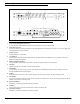
Reference View 1 2 3 4 5 9 6 7 8 15 12 10 11 17 13 14 16 20 18 19 21 FIGURE 1. 8 MS-4002 Reference View 1. Auto-sensing Mic Headset Connector Accepts headsets with monaural headphones; either dynamic and electret microphone. 2. Panel Mic Connector Accepts an electret gooseneck microphone. The model MCP-90 series panel mic connector is a 1/4” stereo plug, with a threaded shaft for easy installation. 3. Volume Control Adjusts headphone volume only. 4.
13. Speaker Volume Control Volume control adjusts the level to the front panel speaker. If an external speaker is used, volume must be adjusted at the speaker. 14. Channel Status Indicators The indicators are green for normal operation and red when there is an overload or short circuit. Once the fault is resolved, the system will Auto-reset. 15. Universal AC Power Input The MS-4002 accepts any input power in the range of 100-240 VAC, 50/60 Hz. 16.
Default Jumper Settings JP1 JP5 pin 1 pin 1 pin 1 JP4 JP6 FIGURE 2. NOTE: JP7 pin 1 JP3 pin 1 Default Jumper Settings These jumpers settings apply only to board 9030-7799-000 Rev G or higher.
CHAPTER 2 Installation Direct Program Listen Enable/Disable By default, each MS-4002 program input can be heard locally by all intercom stations. Program input routing to the intercom channels can be turned on or off via the MS-4002 front panel programming. For more information on programming, see “Standard Programming” on page 21 and “Advanced Programming Using the MS-4002” on page 22. Mounting The MS-4002 mounts in a standard 19-inch equipment rack and is 1 RU (Rack Unit) high.
External Program Input and PA Output Connections for external program input and PA output are shown in Figure 1, EMS-4001 Expansion Station Connection (optional component). REFERENCE:Refer to the EMS-4001 User Instruction Manual (p/n 93507713000) for detailed connection information.
BAL / UNBAL buttons Figure 2. MS-4002 Back Panel Balanced and Unbalanced Operation Switches Default: Balanced (BAL) Operation (Out) Switch position: out (not depressed) Balanced (Audiocom) Switch position: in (depressed) Unbalanced (Clear-Com) Cables The numbers below correspond to the cable numbers in the connection drawings shown in Figure 3. 1. 1-channel intercom cable. Sold separately. Use Telex ME cables, below. ME-25: 25’ (7.6 m) cable with Male and Female 3-pin XLR connectors. ME-50: 50’ (15.
8. Shielded audio cable. Must have male 3-pin XLR connector at one (1) end for connection to the XP-USPG PA output. Pin-out for PA output as follows: Pin 1: Pin 2: Pin 3: 9. common + PA output - PA output 18” (457 mm) CHANNEL OUTPUT cable, 15-pin Male D-sub to 15-pin Female D-sub. One supplied with each XP-ES4000. REFERENCE:Optional component, see EMS-4001 User Manual (p/n 93507713000) for more detailed connection information.
Sidetone Adjustment The MS-4002 uses full-duplex audio (the same as a conventional telephone line) in which the talk and listen audio are sent and received on the same line. When you talk on a channel, you hear your own voice in the speaker or headphones. This is called sidetone. If you are using the MS-4002 with a microphone and speaker, sidetone could cause unwanted feedback, since the microphone may pick up your returned voice audio and re-amplify it.
If you are using headphones that completely enclose the ears, adjust sidetones as follows: 1. Tap the Headset key to turn the headset microphone on. 2. Tap the channel 1 Talk key to turn it on. 3. While speaking into the microphone, use a small flat-bladed screwdriver to adjust the channel 1 Talk key to turn it so you hear your voice at an acceptable level in the headphones. 4. Tap the channel 1 Talk key to turn it off when finished. 5.
CHAPTER 3 Operation Operation NOTE: A quick-reference to the following operating features are shown in Table 5. Normal vs. Programming vs. Advanced Programming Mode The MS-4002 has three operating modes: normal operating mode, standard programming mode (see page 21), and advance programming mode (see page 22). In normal operating mode, the Mic Kill key will be unlit, and in programming mode it is lit continuously.
Volume Adjustment If you are using a headset, adjust the intercom listen level with the left volume control on the front panel of the MS-4002. If you are using a speaker, adjust the intercom listen level with the right volume control next to the speaker. External speakers requires their own volume controls. Receiving Calls 1. When there is an incoming call signal on a channel, the Call key for that channel flashes red.
All Talk You can talk to all intercom stations that currently have their listen keys activated. This applies to all channels of the MS-4002, as well as all the talk channels of any EMS-4001 Expansion Stations. To use the all talk function, do the following: NOTE: If you are using manual microphone activation instead of Vox, make sure the proper microphone switch is turned on (either Headset or Panel Mic). 1. Press and hold the All Talk key while talking. 2. Release the All Talk key when finished.
Using Mic Kill If the Mic Kill feature has been enabled, you can use it to deactivate all talk keys on a single channel or on all channels. This feature is useful when a remote talk key has been left ON and is causing unwanted noise on a channel. To use Mic Kill, do the following: 1. Tap the Mic Kill key. It blinks green. 2. Tap the Talk or Listen key for a channel to turn off all talk keys on that channel. Or, tap the All Talk key to turn off all talk keys.
Standard Programming Standard programming without entering program mode on the MS-4002 To enter Standard Programming, do the following: 1. Press and hold the Mic Kill key for about two (2) seconds, then release it. It glows green to indicate the intercom station is in programming mode.. TABLE 5. Standard Programming Descriptions.
Advanced Programming Using the MS-4002 Advanced Programming for the MS-4002 has moved from the Internal DIP switches (MS-2002 and previous models) to the front panel of the unit. Using Figure 6 you can program your MS-4002 with existing and new functionality. Figure 6. Advanced Programming Buttons Diagram To access Advanced Programming Mode on the MS-4002, do the following: > NOTE: Press and hold both Mic Kill and PA for five (5)seconds.
Call Signal Send and Receive, Channel 2 The Call Signal Send and Call Signal Receive has been combined into one (1) function that is enabled and disabled. Default Setting: Call Signal Send and Receive, Channel 2 enabled. To enable the Signal Send and Signal Receive for Channel 2, do the following: > Press Channel 2 Call button. The button is backlit with a bright red light. The Signal Send and Signal Receive for Channel 2 is enabled.
Program Interrupt 1 NOTE: You must turn PGM Input on before using Program Inputs, see “Turning the Program Input On and Off” on page 19 Default: Program 1 Interrupt is disabled. To enable Program 1 Interrupt, do the following: > Press Channel 1 Talk button. The button is backlit with a bright green light. The Program 1 Interrupt is enabled. To disable the Program 1 Interrupt, do the following: > When lit green, press Channel 1 Talk button. The green back-light dims. The Program 1 Interrupts disabled.
Incoming Call Beep, Headset Default: Incoming Call Beep, Headset Enabled (on) To enable the Incoming Call Beep, do the following: > Press the Headset button. The key is backlit with a bright red light. Incoming Call Beep, Headset is enabled. To disable the Incoming Call Beep, Headset, do the following: > When lit red, the Headset button. The key is backlit with a dim green light. Incoming Call Beep, Headset is disabled.
Listen 4 to Speaker 1 Default: Listen 4 to Speaker 1 Disabled (off) To enable Listen 4 to Speaker 1, do the following: > Press the Channel 4 Listen button. The key is backlit with a bright green light. Listen 4 to Speaker 1 is enabled. To disable the Listen 4 to Speaker 1, do the following: > 26 Press the Channel 4 Listen button. The green back-light dims. Listen 4 to Speaker 1 is disabled.
Specifications General Power Requirements AC Input: 100-240VAC, 50/60Hz Channel Power: 24VDC nominal (12 - 30VDC), up to 1Amp per channel (max. 3.5 Amps) Dimensions 1.75” (44.5mm)high x 19” (483mm) wide x 11.25” (286 mm) deep Weight Approximately 5lb. (2.
PA Output Output Level 235mV nominal Connector Type 3.5mm Stereo Phone Jack Tip: Ring: Sleeve: PA output high Not Used Common Speaker Output Output Level 0dBu nominal (1.0Vrms max) Output Impedance 1000 Ohms Frequency Response 200Hz to 8kHz +1/-3dB Connector Type RCA Phono Jack Tip: Sleeve: Speaker output high Common Expansion Input/Output Type 3.