
Use And Care Manual


18
Assembly
ATTACHING THE GUARD ASSEMBLY
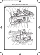
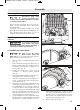
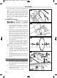
9. With one hand, hold the front of the bar-
rier guard assembly by the “fork” 4. With
the other hand, hold the guard release
lever 5 up (Fig. 7).
10. Lower the rear of guard assembly and slip
the cross bar 6 into the rear notch 7 on top
of the riving knife 2 (Fig. 7).
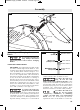
11. Lower the front of the guard assembly
until the “fork” is parallel with the table
(Fig. 8).
12. Press down on the guard release lever
until you feel and hear it snap into the lock-
ing position. Check that the guard assem-
bly is securely connected (Fig. 8).
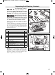
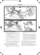
ATTACHING THE ANTI-KICKBACK DEVICE
13. Attach the anti-kickback device 7 into the
flat recessed area 8 of the riving knife 2
(Fig. 9).
14. Squeeze the compression pins 9 while
nesting the device into the flat area
(Fig. 9).
15. Release the compression pins such that
the anti-kickback device locks onto the riv-
ing knife immediately behind the guard as-
sembly. Check that the attachment pin is
securely connected into locking hole.
Carefully raise and lower the pawls 10 –
when letting go, the spring-loaded pawls
must come down and contact the table in-
sert (Fig. 9).
Tip: Position the Anti-kickback device behind
the flat recessed area and slide it towards the
front until it drops into the recessed area –
then release the compression pins.
Note: The two attachments are independant
of each other, so the anti-kickback device can
be attached before the Guard Assembly.
6 7
5
1
2
4
A
B
Fig. 7
5
4
A
B
Fig. 8
1600A01Z1U.qxp_4100XC 10/31/19 1:21 PM Page 18