
Technical information

- 29 -
3
54
55 56
Workshop Manual_3 - 4 LD_cod. ED0053025560_4° ed_ rev. 03
Disassembly / Reassembly
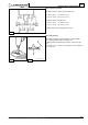
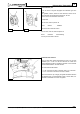
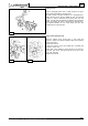
Speed governor
It has a centrifugal system with 6 balls housed in the gear,
which is directly operated by the drive shaft.
The balls, moved at the gear periphery by a centrifugal force,
axially shift the bell 3, which actuates the fork 2 connected
to lever 1 in order to determine the injection pump rack rod
position. A spring with two plates 4, energized by the accelerator
control 5, opposes the action of the governor cetrifugal force.
The balance between the two forces keeps the rpm rate
constant with the change of load.
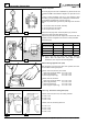
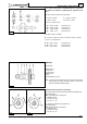
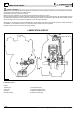
Timing of the speed governor
Adjust the injection pump control lever 1 thus, when the
governor is closed, it is placed at distance A as to the external
surface of the base.
- Loosen the screw 2.
- Close the governor (move the mobile bell 3 towards the
operator, picture 55).
- Place lever 1 at A distance, picture 56 (22 mm for 3LD 450,
3LD 510, 3LD 451/S, 3LD 510/S and 28 mm for 4LD 640,
4LD 705, 4LD 820).
- Tighten the screw 2.