660 EF/EFO INDOOR MODEL/OUTDOOR MODEL Installation must conform with local codes, or in the absence of local codes, the National Fuel Gas Code, ANSI Z223.1/NFPA 54. When applicable, installation must conform with the Manufactured Home Construction and Safety Standard, Title 24 CFR, Part 3280 or the Canadian Standard CAN/CSA-Z240 MH Mobile Homes, Series M86.
Index Index 1 Important Safety Information 2 2.1 2.2 2.3 2.4 2.5 Appliance details Features Specifications (Technical data) Before Installation Dimensions (660 EF) Dimensions (660 EFO) 7 7 8 9 10 10 3 3.1 3.2 3.3 3.4 3.5 3.6 3.7 3.8 3.9 3.10 3.
Important Safety Information 1 Important Safety Information To prevent damage to property and injury to the user, the icons shown below will be used to warn of varying levels of danger. Every indication is critical to the safe operation of the water heater and must be understood and observed. Potential dangers from accidents during installation and use are divided into the following four categories. Closely observe these warnings; they are critical to your safety.
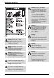
Important Safety Information Warning: BEFORE OPERATING smell all around the water heater area for evidence of leaking gas. Be sure to smell next to the floor because some gas is heavier than air and will settle on the floor. WHAT TO DO IF YOU SMELL GAS: - Do not try to light any appliance. - Do not touch any electrical switch; do not use any phone inyour building. - Immediately call your gas supplier from a neighbor’s phone. Follow the gas supplier’s instructions.
Important Safety Information Warning: Explosion Hazard! If the temperature and pressure relief valve is dripping or leaking, have a qualified service technician replace it. Do not plug or remove the valve. Failure to follow these instructions can result in fire or explosion, and personal injury or death. Warning: Check the temperature of the running hot water before entering the shower. Check the temperature before stepping into the bath tub.
Important Safety Information Warning: Contact Bosch before using with a solar pre-heater. Caution: Do not turn off the water heater while someone is bathing. Warning: California Proposition 65 lists chemicalsubstances known to the state to cause cancer, birth defects, death, serious illness or other reproductive harm. This product may contain such substances, be their origin from fuel combustion (gas, oil) or components of the product itself.
Appliance details Caution: Do not run water through the unit when unit is not on. When discharging hot water, make sure the unit is ON. If water is run through the unit with the unit OFF, water may condense inside the unit and cause incomplete combustion or damage to the internal electrical components. For single-handle fixtures or valves, discharge water setting the handle completely to the water side. Caution: This unit is only approved for installation up to 1350m (4500 ft.) above sea level.
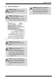
Appliance details 2.2 Specifications (Technical data) Approved in US/Canada Capacity Maximum flow rate: 5.3 GPM (20 l/min) at a 45°F (25°C) rise. Maximum Input 140,000 Btu/h (41,03 kW) Minimum Input 20,000 Btu/h (5.67 kW) Temperature Control Selection range: 100°F (37°C) - 160°F (70°C) Safety devices • Flame Rod • Thermal Fuse • Lightning Protection Device (ZNR) • Overheat Prevention Device • Freezing Prevention Device • Fan Rotation Detector.
Appliance details 2.3 Before Installation Danger: Checkup! Check the fixing brackets and vent pipe yearly for damage or wear. Replace if necessary. Caution: Check Water Supply Quality! If the water supply is in excess of 6 grains per gallon (100 mg/L) of hardness, acidic or otherwise impure, treat the water with approved methods in order to ensure full warranty coverage. Danger: Check the gas! - Check that the rating plate indicates the correct type of gas.
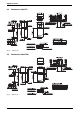
Appliance details 2.4 Dimensions (660 EF) Fig. 4 Dimensions 2.5 Dimensions (660 EFO) Fig.
Installation instructions 3 Installation instructions 3.1 Specialized tools The following specialized tools may be required for installation: • Manometer Max. Straight Vent Length1) 3 15' (4.5m) 2 25' (7.5m) 1 35' (10.6m) Table 2 • Multimeter 1) • Combustion Gas Analyzer. 3.2 No. of elbows Introduction Please follow these instructions. Failure to follow instructions may result in: Not including the termination.
Installation instructions Horizontal Vent Termination Vertical Vent Termination Fig. 6 • Terminate at least 12" (300mm) above grade or above snow line. • Terminate at least 7' (2.1m) above a public walkway, 6' (1.8m) from the combustion air intake of any appliance, and 3' (0.9m) from any other building opening, gas utility meter, service regulator etc. • Terminate at least 3' (0.9m) above any forced air inlet within 10' (3m), 4' (1.2m) below, 4' (1.2m) horizontally from or 1' (0.
Installation instructions Clearance Requirements from Vent Terminations to Building Openings *All clearance requirements are in accordance with ANSI Z21.10.3 and the National Fuel Gas Code, ANSI Z223.1 and in Canada, in accordance with NSCNGPIC. Fig.
Installation instructions 3.3.2 Clearance Requirements from Vent Terminations to Building Openings All clearance requirements are in accordance with ANSI Z21.10.3 and the National Fuel Gas Code, ANSI Z223.1 and in Canada, in accordance with NSCNGPIC. Vent Clearances When Heater is Installed Indoors (For 660 EF appliance) Maintain the following clearances to any opening in any building: • 4' (1.2m) below, 4' (1.2m) horizontally from, or 1' (0.
Installation instructions 3.4 Combustion air requirements Combustion Air Supply combustion air to the units as per the National Fuel Gas Code, ANSI Z223.1 and in Canada, in accordance with NSCNGPIC. • Provide two permanent openings to allow circulation of combustion air. • Make each opening 180 square inches if they provide indoor air, and 100 square inches for outdoor air. • If the unit is installed in a mechanical closet, provide a 24" (600mm) clearance in front of the unit to the door.
Installation instructions Attention residents of the Commonwealth of Massachusetts: In the Commonwealth of Massachusetts the following regulation went into effect on 12/30/2005: signage installed in accordance with the provisions of 248 CMR 5.08(2)(a)1 through 4.
Installation instructions 3.5 Choosing Installation Site Locate the appliance in an area where leakage from the unit or connections will not result in damage to the area adjacent to the appliance or to the lower floors of the structure. When such locations cannot be avoided, it is recommended that a suitable drain pan, adequately drained, be installed under the appliance. The pan must not restrict combustion air flow.
Installation instructions Caution: Make sure that the location allows installation of the exhaust vent as specified. i State of California: The water heater must be braced, anchored or strapped to avoid moving during an earthquake. Contact local utilities for code requirements in your area or call: 1-866-330-2730 and request instructions.
Installation instructions For 660 EFO Required Clearances From Heater • Maintain the following clearance from both combustible and non-combustible materials. * ( ) indicates the distance when installing a heat insulating board (non-combustible material other than metal, with thickness of 0.1" (2.5mm) or more) or "section of building effectively finished with non-combustible material." Note, however, that combustion failure may occur to the unit as exhaust gas reflects from the wall.
Installation instructions 3.7.2 Locating Scew Holes 3.7.5 Caution: B When installing with bare hands, take caution to not inflict injury. B Be careful not to hit electrical wiring, gas, or water piping while drilling holes. 1. Drill a single screw hole, making sure to hit a stud. 2. Insert and tighten the screw and hang the unit by the upper wall mounting bracket. 3. Determine the positions for the remaining four screws (two for the top bracket and two for the bottom), and remove the unit.
Installation instructions 3.8 i Gas piping Follow the instructions from the gas supplier. The appliance and its individual shutoff valve must be disconnected from the gas supply piping system during any pressure testing of that system at test pressures in excess of ½ psig (3.5 kPa). The appliance must be isolated from the gas supply piping system by closing its individual manual shutoff valve during any pressure testing of the gas supply piping system at test pressures equal to or less than ½ psig (3.
Installation instructions Measuring Gas Pressure • In order to check the gas supply pressure to the unit, a tap is provided on the gas inlet. Remove the hex head philips screw from the tap, and connect a manometer using a silicon tube. • In order to check the gas manifold pressure, a pair of taps are provided on the gas valve inside the unit.
Installation instructions Gas Line Sizing For a BOSCH Gas Water Heater 6 720 644 063 23
Installation instructions 3.9 Water piping Installation and service must be performed by a qualified plumber. In the Commonwealth of Massachusetts, this product must be installed by a licensed plumber or gas fitter in accordance with the Massachusetts Plumbing and Fuel Gas Code 248 CMR Sections 2.00 and 5.00. Observe all applicable codes. This appliance is suitable for potable water and space heating applications. Do not use this appliance if any part has been underwater.
Installation instructions Supply water piping Description Max. Levels • Do not use PVC, iron, or any piping which has been treated with chromates, boiler seal or other chemicals. Zinc 5 mg/L or less • Mount a check valve and a shut off valve (near the inlet). Residual chlorine • In order for the client to use the water heater comfortably, 29 to 70 psi of pressure is needed from the water supply. Be sure to check the water pressure.
Installation instructions Comercial Use Treatment Guidelines Type of Water Hardness Level Treatment Device Flush Frequency 1) Soft 0-1 gpg (0-17 mg/L) None None Slightly Hard 1-3 gpg (17-51 mg/L) None None Moderately Hard 3-6 gpg (51-100 mg/L) Water Softener Suggested Once a Year2) Hard 6-10 gpg (100-171 mg/L) Water Softener Suggested Twice a Year3) Very hard 10-14 gpg (171-239 mg/L) Water Softener Softener Required Extremely Hard > 14 gpg (> 239 mg/L) Water Softener Softener Req
Installation instructions 3.11 Plumbing Applications Refer to section 11 for Limited Warranty. Fig. 25 Fig.
Electrical Wiring 4 Electrical Wiring 4.1 Electrical wiring i Warning: Tie the redundant power cord outside the water heater. Putting the redundant length of cord inside the water heater may cause electrical interference and faulty operation. Consult a qualified electrician for the electrical work. Warning: Do not connect electrical power to the unit until all electrical wiring has been completed.
Electrical Wiring 4.2 Remote Controller Applicable Model 6. Replace the front cover of the water heater (4 screws). 660 EF (O) Remote Controller BRC01US for USA, BRC01CA for Canada Table 7 i 5. Connect the temperature selection wire labeled "160°F" to the circuit board as shown on the right. Install the remote controller according to the instructions in section 4.3 (page 31).
Electrical Wiring • Be sure to hand tighten when screwing to the terminal block. Power tools may cause damage to the terminal block. Included Parts List Part Name Quantity Remote controller cord Remote Controller 1 • For extensions, a 26' (7.8m) cord can be purchased (Part # BRC26CORD) or use 18AWG wire. Wall Packing 1 • Install according to the National Electrical Code and all applicable local codes. Phillips Roundhead Wood Screw 2 Wall Anchor 2 1.
Electrical Wiring 3. Insert the wall pipe containing the remote controller wires through the hole. 4. Slide the junction box packing and the junction box over the remote controller wires and wall pipe protruding from the outside wall. Fig. 31 3. Remove the cover of the remote control, mark the location of the screw holes, and drill holes for the wall anchors. 4. Insert the wall anchors, screw the remote control to the wall and replace the cover. Fig. 34 5.
Electrical Wiring Fig. 36 Tie the redundant length of the remote controller cord outside the junction box. 7. Close the junction box.
Operation instructions 5 Operation instructions i 5.1 The installer should test operate the unit, explain to the customer how to use the unit, and give the owner this manual before leaving the installation. Trial Operation Preparation 1. Open a hot water fixture to confirm that water is available, and then close the fixture. 2. Open the gas supply valve. 3. Turn on the power supply. Using the remote controller, turn on the PowerOn/Off button (the Operation lamp will turn on). 4.
Operation instructions 3. Open the gas supply valve. CLOSED OPEN Fig. 39 closed and open on valves 4. Turn on the power. Warning: Do not touch with wet hands. 5.3 How to Use (Not using the remote controller) Setting and Using the Water Heater The factory temperature setting is 120 °F (50 °C) (fixed). Mix with cold water with a mixing valve or at the fixture for desired temperature. 1. Check that electrical power is connected. 2. Turn on hot water. 3. Mix for desired temperature. 4.
Operation instructions 5.4 How to Use (Using the remote controller) Setting and Using the Water Heater The illustration below shows the remote controller display. What is actually displayed depends on how the water heater is set. i USA REMOTE CONTROL (PART N# BRC01US) CANADA REMOTE CONTROL (PART N# BRC01CA) Fig.
Operation instructions Danger: To prevent scalding Do not allow anyone to change the water temperature while hot water is running. The alarm will sound when the set level has been reached. Stop the water. i 2. Set temperature Always check the temperature setting before use. Check the indicator lights. 3. Turn ON hot water 4. Turn OFF the hot water. i An alarm will sound for ten seconds when the flow reaches the set level. The water will continue to run unless it is manually turned off.
Maintenance and service 6 Maintenance and service i Periodically check the following to ensure proper operation of the water heater. • The venting system must be examined periodically by a qualified service technician to check for any leaks or corrosion. • The burner flame must be checked periodically for a proper blue color and consistency. • If the flame does not appear normal, the burner may need to be cleaned.
Maintenance and service 6.2 Preventing Damage from Freezing Caution: Damage can occur from frozen water within the device and pipes even in warm environments. Be sure to read below for appropriate measures. Caution: Repairs for damage caused by freezing are not covered by the warranty. Freezing is prevented within the device automatically by the freeze-prevention heater Freezing cannot be prevented when the power plug is unplugged.
Maintenance and service 4. When the water is flowing again, check for water leaks from the equipment and piping before using. If the heater or the piping is frozen, do not use the heater or it may get damaged. If the water heater will not be used for a long period of time, drain the water Drain the water as follows: Caution: To avoid burns, wait until the equipment cools down before draining the water.The appliance will remain hot after it is turned off. Drain water into a bucket to prevent water damage.
Troubleshooting 7 Troubleshooting 7.1 Initial Operation Unit does not attempt to ignite when water is running. Check for reversed plumbing or crossed pipes. Unit attempts to ignite but fails. Reset unit and try again. There may be air in the gas line. Check the water drain valve filter. Have a professional check the gas supply pressure. Table 9 7.2 Temperature Hot water is not available when a fixture is opened.
Troubleshooting The water is not hot enough. Is the gas supply valve fully open? (Using the remote controller) Is the water temperature setting appropriate? If the amount of hot water required is very high, it is possible for the temperature to be lower than the temperature set on the remote controller. Decrease the amount of hot water passing through the unit and the temperature should stabilize. The water is cold when only a single fixture is open.
Troubleshooting 7.4 Remote Controller The light on the power button does not come on. Has there been a power failure? The water temperature changes after a power failure or when the power is disconnected. The temperature setting and the flow meter alarm setting may both need to be reset after a power outage. The plastic on the surface or buttons of the remote controller has torn, peeled, or air bubbles inside.
Troubleshooting 7.6 Others The heater stops burning during operation. Are the gas and water supply valves fully open? Is the water supply cut off? Is the hot water fixture sufficiently open? Is the gas being cut off by the gas meter? (Can other gas devices such as stoves be used?) (For LP) Is there enough gas in the tank? (Can other gas devices such as stoves be used?) White smoke comes out of the exhaust vent (terminal) on a cold day. This is normal. The white smoke is actually steam.
Troubleshooting 7.7 Check for an Error Code (Using the remote controller) Error displays on the remote controller If there is a problem with the unit, a numerical error code will flash on the remote controller. If this occurs, take appropriate measures as listed below. When an error code appears, the display and the operation light will flash together. Fig. 44 Error Code Cause Action Ignition error. Check whether the gas valve is open.
Follow- up Service 8 Follow- up Service 8.1 Requesting Service Warning: Before the gas conversion is performed, verify the proper gas conversion kit with your water heater model on the table provided below. First follow the instructions in the troubleshooting section. If the error is not corrected, contact Bosch Thermotechnology Corp. at 1-866-330-2730.
Interior components diagram 9 Interior components diagram 9.1 660 EF Interior components Fig.
Interior components diagram 9.2 660 EFO Interior components Fig.
Protecting the environment 10 Protecting the environment Packing The packing box may be fully recycled as confirmed by the recycling symbol . Components Many parts in the heater can be fully recycled in the end of the product life. Contact your city authorities for information about the disposal of recyclable products. Saving water resources: B Make sure you close all the taps after any use. Avoid leaving the taps dripping. Repair any leaking tap.
Limited Warranty 11 Limited Warranty General Service Labor Costs BOSCH PRO tankless water heaters are warranted by the Manufacturer (BOSCH) through Bosch Thermotechnology Corp. Bosch Thermotechnology Corp. will furnish a replacement heat exchanger and will furnish a replacement of any other part which fails in normal use and service within the applicable periods specified below, in accordance with the terms of this warranty. The Bosch Thermotechnology Corp.
Limited Warranty 50 6 720 644 063
Limited Warranty 6 720 644 063 51
Installer Checklist to be completed by installer upon installation Serial Number ___ ___ ___ ___ ___ ___ ___ ___ (8 digit serial number is located on rating plate on right side panel) Gas Pressure Reading Static__________ Operating__________ Building Water Pressure __________ Range if on Well system __________ Installing Company _____________________________________________ Installer name _____________________________________________ Address _____________________________________________ Phone