Revision 1.
Bosch Alarm Panel Interface Manual Revision 1.4 This document is a System Galaxy Product Interface manual. Information in this document is subject to change without notice. No part of this document may be reproduced, copied, adapted, or transmitted, in any form or by any means, electronic or mechanical, for any purpose, without the express written consent of Galaxy Control Systems.
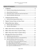
Bosch Alarm Panel Interface Manual Revision 1.4 Table of Contents 1 2 Introduction .................................................................................. 5 1.1 Overview of System Galaxy Alarm Panel Interface.............................................5 1.2 About the Bosch Alarm Panel ..............................................................................6 1.3 How System Galaxy communicates with the Alarm Panel.................................6 1.
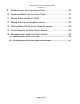
Bosch Alarm Panel Interface Manual Revision 1.4 9 Getting Events from the Alarm Panel ........................................ 30 10 Command Menus for the Alarm Panel....................................... 31 11 Device Status for Alarm Panel................................................... 32 12 Adding Icons for the Graphics screen........................................ 33 13 Placing Alarm Points on the Graphics screen ........................... 34 14 Crystal Reports for Alarm Panel Events .......
Bosch Alarm Panel Interface Manual Revision 1.4 1 Introduction This manual describes registration, setup, and operation of the System Galaxy Alarm Panel Interface to the Bosch Alarm Panel. This manual also includes specific information about alarm panel settings that are required in order to connect with System Galaxy 7.2 or higher (covered in section 2.1). This manual does not replace or supersede the manufacturer’s manual.
Bosch Alarm Panel Interface Manual Revision 1.4 1.3 The Bosch Alarm Panel from a Galaxy perspective Bosch has alarm inputs called “points” at the panel wiring terminals. Refer to Bosch product manual. (Points can be defined in System Galaxy to reflect the true alarm panel programming.) Several points can be configured to represent an “Area”. Refer to Bosch product manual for details. (Areas can be defined in System Galaxy to reflect the true alarm panel programming.
Bosch Alarm Panel Interface Manual Revision 1.4 1.5 Overview of System Galaxy’s GCS Alarm Panel Service The GCS Alarm Panel Service (AP Service) runs as a true background service and supports encryption. See Section 8 – Managing the Alarm Panel Service. The AP Service should be set up to start automatically and must be running to support logging of alarm panel status/events. When the service is running, a gray Panel Icon will appear on the system tray of the PC.
Bosch Alarm Panel Interface Manual Revision 1.4 2 Configuring System Galaxy The following steps are required to properly setup System Galaxy to interface with the alarm panel. Step Action Reference 1 All installation, wiring and programming of the Alarm Panel should be completed before configuring System Galaxy. The Alarm Panel should be installed and fully configured before configuring System Galaxy.
Bosch Alarm Panel Interface Manual Revision 1.4 2.1 Physically Connecting to the Alarm Panel STEP 1: Install and program the Alarm Panel according to the Manufacturer’s Instruction The Alarm Panel should be installed and fully configured before connecting to System Galaxy. STEP 2: Connect the Alarm Panel to the System Galaxy Communication Server/PC Bosch 9000/7000 Series alarm panels can connect to the SG Communication PC by three possible choices described below.
Bosch Alarm Panel Interface Manual Revision 1.4 3 Register System Galaxy for Alarm Panel The alarm panel is registered in the System/Product Registration screen. This screen can be opened through the Registration Wizard (first screen) or the System Registration screen. STEP 3: Register System Galaxy for the Alarm Panel Support: Open the System Galaxy software by double-clicking on the SG icon located on the PC desktop of the Communication Server.
Bosch Alarm Panel Interface Manual Revision 1.4 4 Setting Workstation Options This section describes setting up Workstation Options that are related to alarm features. The settings for alarm options and the path to the alarm icons are set in the Workstation Options screen. 4.1 Setting the path to the Alarm Icons The multi-media path to the alarm icons must be set to the correct directory for the system to find the correct graphics used in mapping and displaying status of alarms (see section 4.1).
Bosch Alarm Panel Interface Manual Revision 1.4 4.2 Setting the Alarm Options Workstat0ion alarm options determine how the Workstation behaves when Alarm Events occur for acknowledgeable alarms. An acknowledgeable alarm is defined as ‘a detected event that meets the criteria (device programming) to trigger an SG Alarm Event’. Acknowledgeable alarms may or may not generate an SG Alarm Event depending on the condition and also on local workstation option settings.
Bosch Alarm Panel Interface Manual Revision 1.4 5 Add an Alarm Panel in System Galaxy The alarm panel must be added in the System Galaxy software before the GCS Alarm Panel Service will connect to the panel. The programming must match the Alarm Panel configuration. After Panel, Areas and Points are added, System Galaxy can begin receiving status events from the alarm panel. The alarm panel events are displayed in the Alarm Panel Event screen.
Bosch Alarm Panel Interface Manual Revision 1.4 Additional Utilities explained on this page … Also in the Alarm Panel Property screen are remote configuration options for the alarm panel. These are utility features that allow the operator to send commands or data to the selected Alarm Panel. Virtual Keypad = allows operator to mimic typing at the Bosch keypad. Allows up to 8 keypads. Allows operator to interface with the Bosch Alarm panel from System Galaxy.
Bosch Alarm Panel Interface Manual Revision 1.4 6 Add an Alarm Panel Area in System Galaxy The Alarm Panel Area should be added in the System Galaxy software. The programming must match the Alarm Panel Area configuration. An alarm panel area consists of 1 or more points After Panel, Areas and Points are added, System Galaxy can begin receiving status events from the alarm panel. (Note the alarm panel connection The alarm panel events are displayed in the Alarm Panel Event screen.
Bosch Alarm Panel Interface Manual Revision 1.4 7 Add an Alarm Panel Point in System Galaxy The alarm panel point must be added in the System Galaxy software. The programming must match the Alarm Point configuration at the Alarm Panel. After Panel, Areas and Points are added, System Galaxy can begin receiving status events from the alarm panel. The alarm panel events are displayed in the Alarm Panel Event screen.
Bosch Alarm Panel Interface Manual Revision 1.
Bosch Alarm Panel Interface Manual Revision 1.4 Graphic Symbols tab (if using the Graphics screen) Allows operator to configure which icons represent each Alarm Panel status condition. User can choose the condition from the drop list and select an available graphic from the default directory or browse to a directory where graphics are stored.
Bosch Alarm Panel Interface Manual Revision 1.4 DVR Camera Settings tab Allows operator to link status events from this alarm Point to a DVR unit and camera. When this option is configured, the system associate a camera with the designated alarm point. When programmed, the operator will be able to initiate DVR Viewing within system galaxy for the alarm point.
Bosch Alarm Panel Interface Manual Revision 1.4 CCTV Events tab Allows operator to set CCTV parameters to be sent to CCTV system. Alarm number = must be greater than zero; allows user to set the number to send to the CCTV service/system. Zero means no alarm message is sent to CCTV system. Camera, Monitor, Position, fields allow SG to send commands to CCTV system. Manual command = if programmed, the user can send commands from the short menu in the hardware tree.
Bosch Alarm Panel Interface Manual Revision 1.4 8 Managing GCS Alarm Panel Service GCS Alarm Panel Service runs as a true background service and should be set up to start automatically when the PC starts. The AP Service icon displays a gray alarm panel icon in the system tray. IMPORTANT: the AP Service has a dependency to the DBWriter service and drops its connection to the alarm panel if the DBWriter is offline. The DBWriter Service must be running to receive events.
Bosch Alarm Panel Interface Manual Revision 1.4 8.1 Starting the Alarm Panel Service After the Alarm Panel is configured and the necessary GCS Services are running, System Galaxy can begin receiving alarm panel status messages. The Alarm Panel Service should be configured to start up automatically when the PC boots up (section 8.2) and to automatically connect to the alarm panel ). Operator can manually connect to the alarm panel from the Alarm Panel Service window (see section 8.3.3 part 4).
Bosch Alarm Panel Interface Manual Revision 1.4 FIG 9: SG Communication Server/PC: Services window OPEN THE MANAGE SERVICES WINDOW, USER WILL SCROLL DOWN TO THE DESIRED SERVICE AND HIGHLIGHT IT (WITH A SINGLE-LEFT-MOUSE CLICK). THEN USER WILL RIGHT-CLICK THE SERVICE TO GET THE SHORT MENU. THEN, THE USER WILL CLICK THE ‘START’ OPTION TO START THE SERVICE. THE GCS ALARM PANEL SERVICE ICON DISPLAYS ON PCS SYSTEM TRAY WHEN SERVICE IS STARTED/RUNNING 8.
Bosch Alarm Panel Interface Manual Revision 1.4 8.3 About the GCS Alarm Panel Server (service) The GCS Alarm Panel service automatically connects to an alarm panel if the alarm panel is properly installed, registered, and configured in System Galaxy. Registration and setup are described in the following sections. This section includes pertinent notes about how the GCS Alarm Panel service works.
Bosch Alarm Panel Interface Manual Revision 1.4 8.3.1 GCS Alarm Panel Service system requirements The following information should be considered in addition to the General System Requirements to run System Galaxy with services. See the System Recommendations for SG-7 document for general system requirements.
Bosch Alarm Panel Interface Manual Revision 1.4 8.3.3 How to connect to the Alarm Panel The GCS Alarm Panel Service reads the alarm panel configuration from the SG database and begins making attempts to auto-connect to the panel at least 60 seconds after the configuration is saved. Part 4: Connect to the Alarm Panel manually as well as view/edit connection properties: The Alarm Panel Connections tab shows an IP connection for each alarm panel that has been configured in System Galaxy.
Bosch Alarm Panel Interface Manual Revision 1.4 8.3.4 Managing Properties of the Alarm Panel Connection User can edit the IP parameters and connection settings from the Connection Properties window. User can also configure the encryption settings from this window. FIG 11b: Connection Properties screen The parameters in this screen are originally programmed in the Alarm Panel Properties screen and saved in the SG database (Refer to Section 5).
Bosch Alarm Panel Interface Manual Revision 1.4 8.3.5 How to see and manage the IP connections between services The TCP/IP Connections tab shows the incoming and outgoing IP connections between GCS Services. The ClientGW Service and the DBWriter Service should each show a connection in this screen. There should only be one Client Gateway connection even if the system has more than one client.
Bosch Alarm Panel Interface Manual Revision 1.4 8.3.6 Log File for GCS Alarm Panel Service The AP Service creates a log file of connection status messages. This is log of connection attempts between the Service and the Alarm Panel as well as other messages. This text file is stored in the System Galaxy\Log Files folder. The buffer of recent entries is viewable in the GCS Alarm Panel screen on the Status Messages tab.
Bosch Alarm Panel Interface Manual Revision 1.4 9 Getting Events from the Alarm Panel System Galaxy displays alarm panel status messages in the Alarm Panel Event screen. If the system is registered for the alarm panel then the Alarm Panel Event screen will open when the software opens. When all the necessary GCS Services are running and the alarm panel is connected to the Alarm Panel service, then System Galaxy can start receiving live events from the alarm panel.
Bosch Alarm Panel Interface Manual Revision 1.4 10 Command Menus for the Alarm Panel Shortcut command menus are available when user right-mouse-clicks the icons from the hardware tree. The alarm panels will be displayed as a branch in the hardware tree. From the Alarm Panel Icon, the operator can expand and see the Alarm Panel and its Areas and Points. NOTE: Alarm Panel commands are also available from the Graphics Screen, Device Status screen and the Alarm Panel Event screen.
Bosch Alarm Panel Interface Manual Revision 1.4 11 Device Status for Alarm Panel System Galaxy supports device status, which includes command menus. • open the Device Status screen from the main menu: select View > Device Status • click the [Add New] button and type a descriptive name • click the Alarm Panel Points tab • pick the points you wish to create a view for and move them to the INCLUDE list • click [Apply] and [OK] Once you have created the view, the Device Status screen will open.
Bosch Alarm Panel Interface Manual Revision 1.4 12 Adding Icons for the Graphics screen NEW FEATURE – System Galaxy provides a standard set of icons, and allows the user the ability to import additional icons. These icons are mapped to each of the status conditions in the Alarm Point programming screen. After mapping the status conditions to the desired graphic symbols, the symbols can be dropped onto the Graphics screen. NOTE: Bitmap (.bmp) icons of any size can be imported.
Bosch Alarm Panel Interface Manual Revision 1.4 13 Placing Alarm Points on the Graphics screen The System Galaxy Graphics screen is typically opened to a floor plan image and icons are dropped onto the Graphics screen (i.e. floor plan) in the locations that represent the actual alarm points. Once the icons are placed on the Graphic screen, the color graphic they are mapped to will be displayed when the state/condition of the alarm point changes. The process for setting up icons is outlined below: 1.
Bosch Alarm Panel Interface Manual Revision 1.4 14 Crystal Reports for Alarm Panel Events Crystal Reports are available in System Galaxy for the Alarm Panel. The report content depends on which report is chosen. NOTE THAT THE ALARM PANEL DOES NOT RETRANSMIT OFFLINE EVENTS TO THE SG DATABASE. Therefore, the reports only include the “live” status conditions received by System Galaxy when the Alarm Panel is properly connected.
Bosch Alarm Panel Interface Manual Revision 1.4 15 Managing User Codes for Alarm Panels System Galaxy allows operator to set up and manage user codes for the alarm panel. Operator can also assign user codes to cardholders in System Galaxy. 15.1 Managing Alarm Panel User Codes Managing user codes is done in the Alarm Panel User Codes screen. This feature allows the System Galaxy operator to retrieve available IDs from the alarm panel and then add the user code. The code is sent down to the alarm panel.
Bosch Alarm Panel Interface Manual Revision 1.4 15.2 Assigning Alarm Panel User Codes to Cardholders System Galaxy allows the operator to manage user codes for the Cardholder. This is an administrative feature and only one code per cardholder can be configured. To set the user codes see section 15.1. The Alarm Panel User Codes tab in Cardholder screen allows user to associate an alarm panel user code with the cardholder.