
Install Instructions
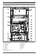
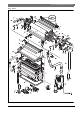
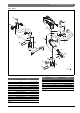
Table Of Contents
- Table of contents
- 1 Key to symbols and safety instructions
- 1.1 Key to symbols
- 1.2 Safety instructions
- 2 FCC rules
- 3 Appliance details
- 4 Installation instructions
- 4.1 Specialized tools
- 4.2 Introduction
- 4.3 Venting
- 4.3.1 Vent material
- 4.3.2 Vent specifications
- Venting specifications
- Condensate drain requirements
- Minimum combustion air and exhaust pipe length
- Maximum combustion air and exhaust pipe length
- Use of elbows
- Calculation example for 3" venting:
- Calculation example for 4" venting:
- Required direct vent terminal clearances (twin pipe / concentric penetration)
- Required other than direct vent terminal clearances (single pipe penetration)
- 4.3.3 Vent configuration examples
- 4.3.4 Vent connections
- 4.3.5 Connecting the condensate water drain
- 4.3.6 Freeze prevention
- 4.3.7 Fan speed adjustment
- 4.4 Combustion air requirements
- 4.5 Proper location for installing your heater
- 4.6 Heater placement and clearances
- 4.7 Mounting installation
- 4.8 Gas piping & connections
- 4.9 Water connections
- 4.10 Water quality
- 4.11 Filling the condensate trap
- 4.12 Domestic hot water recirculation
- 4.13 Space heating applications
- 4.14 Measuring gas pressure
- 5 Electrical connections
- 6 Operation instructions
- 7 Maintenance and service
- 8 Troubleshooting
- 9 Problem solving
- 10 Electrical diagram
- 11 Sensor resistance charts
- 12 Functional scheme
- 13 Interior components diagram and parts list
- 14 Protecting the environment
- 15 Installer Checklist to be completed by installer upon installation

52 | Interior components diagram and parts list
C 1210 ES/ESC6 720 644 887 (2017/05)
13 Interior components diagram and parts list
13.1 Interior components
Fig. 76 Components
[1] Exhaust temperature sensor
[2] Condensing heat exchanger
[3] Heat exchanger
[4] Ionization sensor
[5] Primary fan (Mixer)
[6] LCD display
[7] On/Off button
[8] Reset button
[9] Program key
[10] Flue gas limiter
[11] Heat exchanger overheat sensor (ECO)
[12] Ignition electrodes
[13] Observation window
[14] Backflow temperature sensor
[15] Secondary air fan
[16] Gas valve
[17] Condensate trap
[18] Control unit
[19] Up button
[20] Down button
[21] LED