
Install Instructions
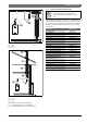
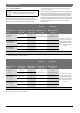
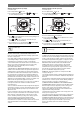
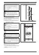
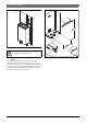
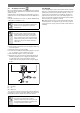
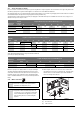
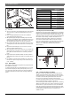
Table Of Contents
- Table of contents
- 1 Key to symbols and safety instructions
- 1.1 Key to symbols
- 1.2 Safety instructions
- 2 FCC rules
- 3 Appliance details
- 4 Installation instructions
- 4.1 Specialized tools
- 4.2 Introduction
- 4.3 Venting
- 4.3.1 Vent material
- 4.3.2 Vent specifications
- Condensate drain requirements
- Twin pipe termination clearances
- Minimum combustion air and exhaust pipe length
- Maximum combustion air and exhaust pipe length
- Use of elbows
- Calculation example for 3" venting:
- Calculation example for 4" venting:
- Required direct vent terminal clearances (twin pipe / concentric penetration)
- Required other than direct vent terminal clearances (single pipe penetration)
- 4.3.3 Vent configuration examples
- 4.3.4 Vent connections
- 4.3.5 Connecting the external condensate water drain
- 4.3.6 Freeze prevention
- 4.3.7 Venting for manufactured (mobile) homes
- 4.3.8 Fan speed adjustment
- 4.4 Combustion air requirements
- 4.5 Proper location for installing your heater
- 4.6 Heater placement and clearances
- 4.7 Hanging appliance on the wall
- 4.8 Mounting installation for manufactured (mobile) homes
- 4.9 Gas piping & connections
- 4.10 Water connections
- 4.11 Water quality
- 4.12 Domestic hot water recirculation
- 4.13 Space heating applications
- 4.14 Measuring gas pressure
- 5 Electrical connections
- 6 Operation instructions
- 7 Maintenance and service
- 8 Troubleshooting
- 9 Problem solving
- 10 Electrical diagram
- 11 Sensor resistance charts
- 12 Functional scheme
- 13 Interior components diagram and parts list
- 14 Protecting the environment
- 15 Installer Checklist to be completed by installer upon installation

Installation instructions | 25
6 720 644 936 (2016/05)830 ES
4.6 Heater placement and clearances
The water heater design is approved for installation on a combustible
wall (see chapter 4.7 Mounting installation) provided the floor covering
below the heater is noncombustible.
For installations in an alcove or closet, maintain the minimum clearances
to combustible and non-combustible materials. See fig. 6, page 10.
4.7 Hanging appliance on the wall
If wall is sheathed with plaster or drywall, it is recommended that two
support boards, either 1"x 4" or 1/2" (minimum) plywood first be
attached across a pair of studs, see fig. 29, page 25.
▶ Secure the wall mounting bracket provided with the heater to a wall
surface. The heater must be kept level on the wall surface, see fig.
30, page 26.
▶ Hang the appliance on the bracket, see fig. 31, page 27.
Fig. 29 Distance between support boards
[1] Studs 16" (406mm) on center
Fig. 30 Leveling wall mounting bracket
NOTICE: Risk of appliance freezing!
▶ The water in this water heater is cold and always
remains cold except for the times the burner is on. In
the event of power outage in conjunction with
freezing temperatures, it is recommended that the
heater be drained.
See chapter 7.2, page 37 “Winterizing” for draining
instructions.
WARNING:
▶ Flammable materials, gasoline, pressurized
containers, or any other items or articles that are
potential fire hazards must NOT be placed on or
adjacent to the heater. The appliance area must be
kept free of all combustible materials, gasoline and
other flammable vapors and liquids.
WARNING: Severe personal injury and property
damage!
Before mounting appliance:
▶ Check that there are no loose or damaged parts
inside the appliance.
▶ Confirm that the gas type of the heater matches the
gas supply you will be connecting the heater, see
Fig.2, page 8.
Front cover should be removed (see instructions on page
8) in order to inspect components visually.
WARNING:
▶ Do not install this appliance on a carpeted wall. The
heater must be mounted on a wall using appropriate
anchoring materials.
NOTICE: Risk of appliance freezing!
▶ In areas where outside temperature is routinely
below 32°F (0 °C) and the heater is to be installed on
the inside of an exterior wall, a minimum 2" air gap or
rigid insulation between the heater back and the wall
is recommended.
6720608158-64.1AL