Continuous Flow Gas Water Heaters (External Models) HydroPower TF250-8G(10H)/ TF325-8G(13H)/ TF400-8G(16H) Installation Manual and Operating Instructions 8 716 473 071 (2015/04) AU Read installation manual prior to installation of this unit! Read user manual before putting this unit in operation! Observe the warnings in the manuals! The installation room must fulfill the ventilation requirements! Installation by an authorised person only!
| Table of contents Table of contents 1 Safety information and symbols . . . . . . . . . . . . . . . . 3 1.1 Key to symbols . . . . . . . . . . . . . . . . . . . . . . . 3 1.2 Safety information . . . . . . . . . . . . . . . . . . . . . 3 2 Technical Characteristics and Dimensions . . . . . . . 2.1 General Description . . . . . . . . . . . . . . . . . . . 2.2 Explanation of Model Code . . . . . . . . . . . . . . 2.3 Package contents . . . . . . . . . . . . . . . . . . . . . 2.4 Product overview . . .
Safety information and symbols | 3 1 Safety information and symbols 1.1 Key to symbols Warnings Warnings in this document are identified by a warning triangle printed against a grey background. Keywords at the start of a warning indicate the type and seriousness of the ensuing risk if measures to prevent the risk are not taken. The following keywords are defined and used in this document: • NOTICE indicates a situation that could result in damage to property or equipment.
| Technical Characteristics and Dimensions 2 Technical Characteristics and Dimensions 2.1 General Description Models Bosch Hydropower TF250/325/400 Category CONTINUOUS FLOW Type GAS - EXTERNAL INSTALLATION Table 2 2.2 Explanation of Model Code TF (Top Flue) 250 (10 litres/min @ 25 °C Rise) G (Hydrogenerator) TF (Top Flue) 325 (13 litres/min @ 25 °C Rise) G (Hydrogenerator) TF (Top Flue) 400 (16 litres/min @ 25 °C Rise) G (Hydrogenerator) Table 3 2.
Technical Characteristics and Dimensions | 5 Low Flow Rates This gas water heater is designed to operate at a minimum flow rate between 3.2 to 4.0 litres per minute. Sufficient flow must be provided to ensure the correct operation of the appliance. There are various causes of a low flow rate including, but not limited to: • Low flow tapware • Flow restrictors/aerators • Hand held showers • Poor inlet pressure to property • Restrictive pipework and/or fittings Water fixtures with a flow rate of 7.
| Technical Characteristics and Dimensions 2.6 Dimensions A 265 1 D 4 4 B 2 E C 3 7 NG: Ø3/4" LPG: Ø1/2" 6 50 5 120 Ø1/2" 120 Ø1/2" 9708069951-01.2V Fig.
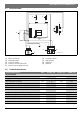
Technical Characteristics and Dimensions | 7 2.7 Electrical scheme 4 5 S 3 HV 2 6 1 9 8 7 9708069951-11.1V Fig. 3 [6] [7] [8] [9] Temperature limiter Hydrogenerator LED (green) LED (red) Units TF250H / 10H TF325H / 13H TF400H / 16H MJ/h 79 104 130 Natural gas (When operating) kPa 1.13 1.13 1.13 LP gas (When operating) kPa 2.75 2.75 2.
| Regulations Technical characteristics Units TF250H / 10H TF325H / 13H TF400H / 16H Temperature selector in fully anti-clockwise position Temperature rise (Above incoming water temperature) Water flow range (Litres per minute) °C 25 25 25 l/min 4 to 10 4 to 13 4 to 16 Minimum operating water pressure kPa 45 45 45 Minimum constant water pressure for maximum flow kPa 100 140 170 Table 5 NOTICE: Property damage! If the appliance is to be installed on a combustible surface: Regulati
Installation | 9 Minimum water supply pressure must meet the requirements set out in table 5. Water fixtures with a flow rate of 7.5 litres per min for hand basins and 9 litres per min for shower roses are recommended. To reduce the chance of corrosion, installation in a marine environment should be avoided. Premature corrosion due to the installation environment would not be covered by warranty. All gas appliances require adequate air intake to ensure correct combustion.
| Installation 4.2 • • • Requirements of the installation location Comply with the specific instructions for each State. Install the appliance in an outdoor location where it will not be exposed to temperatures below zero. Install the appliance in accordance with the minimum installation clearances indicated in Fig. 5, according to AS5601. I c • • The gas heater must not be installed over a heat source. Do not obstruct the openings at top, bottom and rear of appliance.
Installation | 11 Minimum clearances (mm) Ref. Item a b c d e f g h j k n Below eaves, balconies and other projections: 500 - Appliances over 50 MJ/h input From the ground, above a balcony or other surface1) 300 From a return wall or external corner1) 500 From a gas meter (M) (see 5.11.5.
| Commissioning CAUTION: Never rest the gas heater on the water or gas connections. 4.4 the correct pressure to the appliance regulator. The gas pressures require setting upon installation. ▶ Open all water and gas isolation valves. ▶ Purge the pipes. Water connection Purge the water pipes before connection, because the presence of dirt may reduce the flow and, in extreme cases, cause a blockage. ▶ Identify the cold water pipe and the hot water pipe, so as to avoid any possible cross-connection.
Commissioning | 13 5.3 Inlet pressure adjustment DANGER: The following procedures must only be performed by a qualified technician. Gas pressure adjustment (commissioning) MUST be carried out upon installation. ▶ Check the gas indicated on the rating plate and front cover label is the same as the gas to which the heater is connected. ▶ Loosen the pressure test point screw on the left hand side of the gas valve (Fig. 10, [A]) and attach a manometer.
| Operating instructions ▶ Remove manometer and tighten test point screw. Fig. 12 A Fig. 10 For higher water temperature (Fig. 13). Slide to the right will give higher water temperature but use more gas. 9708069951-18.1V Gas pressure measurement point Fig. 13 6.2 B Fig. 11 9708069951-17.1V Consumer temperature/flow adjustment ▶ Turn anti-clockwise Increases flow and decreases water temperature (Fig. 14). Minimum gas flow adjusting screw Natural gas LP gas 0.30 0.
Maintenance | 15 7 Maintenance To ensure ongoing performance and safety, we require the appliance be serviced every two years. DANGER: Failure to perform maintenance procedures can lead to appliance malfunction, errors, service calls and loss of manufacturers warranty. ▶ Your appliance should only be attended by a Bosch authorised service agent. ▶ Only use original replacement parts. Maintenance must only be performed by a qualified technician.
| Troubleshooting 8 Troubleshooting 8.1 Problem/cause/solution Assembly, maintenance, and repairs must be performed by qualified technicians only. The following chart offers possible solutions to problems. In most instances it is advisable to have a technician attend and inspect the appliance. Some further trouble shooting advice may be found at http://www.bosch-climate.com.au Problem Cause Solution Fluctuation in hot water temperature. Insufficient flow through the hot water unit.
Environmental protection | 17 Problem Cause Solution Reduced water flow. Insufficient water supply pressure. Dirty taps or mixers. Water valve blocked (filter). Heat exchanger blocked (limescale). Requires a service technician to inspect and test water supply pressures, and water components of the hot water unit. Unit makes a loud bang when igniting. Explosive ignition is not normal behaviour. Call a qualified technician. Presence of soot/black marks observed at This is not normal behaviour.
| Water quality 10 Water quality All Bosch water heating appliances are constructed from high quality materials and components, and all are certified for compliance with relevant parts of Australian and New Zealand gas, electrical and water standards. While Bosch water heaters are warranted against manufacturing defects, the warranty is conditional upon correct installation and use, in accordance with detailed instructions provided with the heater.
Warranty details | 19 11 Warranty details Robert Bosch (Australia) Pty Ltd Thermotechnology Division Voluntary Repair or Replacement Warranty All Bosch products are carefully checked, tested and certified to Australian and New Zealand standards. Important Note: Mandatory Australian Consumer Law statement If you have purchased your product in Australia, you should be aware that: This warranty is provided in addition to other rights and remedies held by a consumer at law.
| Warranty details "Domestic use" warranty period applies to Product installed to supply hot water for use by individuals in domestic dwellings. For Product used for all other uses, the commercial use warranty period will apply. This includes, without limitation, installations such as centralised or bulk hot systems, hotels, sporting complexes, caravan parks, laundry facilities, restaurants and cafes.
Warranty details | 21 • • as a result of repairs, alterations or modifications to the Product which have been performed by a person who is not suitably qualified and experienced to perform works on the Product; or from the use of any spare parts not manufactured, sold or approved by Bosch in connection with the repair or replacement of Product.
| Warranty details Bosch is committed to protecting the privacy of personal information and will act in compliance with applicable privacy laws, including the National Privacy Principles under the Australian Privacy Act 1988 (Cth) (as amended) and New Zealand’s Information Privacy Principles described in the Privacy Act 1993 (NZ).
| 23 Notes HydroPower 8 716 473 071 (2015/04)