6720808879-00.
| Index Index 1 Key to symbols and safety instructions . . . . . . . . . . 3 1.1 Key to symbols . . . . . . . . . . . . . . . . . . . . . . . 3 1.2 Safety Information . . . . . . . . . . . . . . . . . . . . . 3 2 Product details . . . . . . . . . . . . . . . . . . . . . . . . . . . . . . . 5 2.1 Declaration of Conformity . . . . . . . . . . . . . . 5 2.2 Type overview . . . . . . . . . . . . . . . . . . . . . . . . 5 2.3 Included Items . . . . . . . . . . . . . . . . . . . . . . . . 5 2.
Key to symbols and safety instructions | 3 1 Key to symbols and safety instructions 1.1 Key to symbols Warnings Warnings in this document are identified by a warning triangle printed against a grey background. Keywords at the start of a warning indicate the type and seriousness of the ensuing risk if measures to prevent the risk are not taken. The following keywords are defined and used in this document: • NOTICE indicates a situation that could result in damage to property or equipment.
| Key to symbols and safety instructions • • • Ensuring the appliance performs to the specifications stated on the rating label. Demonstrating the operation of the appliance to the customer before leaving. Handing the operating instructions to the customer. THIS APPLIANCE IS NOT SUITABLE FOR POOL OR SPA POOL APPLICATIONS.
Product details | 5 Safety of electrical appliances for domestic use and similar • purposes The following requirements apply in accordance with EN 60335-1 in order to prevent hazards from occurring when using electrical appliances: 2.4 “If the power cable is damaged, it must be replaced by the manufacturer, its customer service department or a similarly qualified person, so that risks are avoided.
| Product details 2.7 Dimensions and minimum clearances Fig. 1 Dimensions (in mm) A B C D E GWH12 300 570 170 120 107 GWH16 364 570 175 142 137 GWH20 364 570 175 142 137 Table 4 Connections Water Gas Cold Hot Nat.
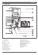
Product details | 7 2.8 Appliance layout Fig.
| Product details 2.9 Fig.
Product details | 9 2.10 Specification Technical features Units GWH12 GWH16 GWH20 Nominal Gas Consumption MJ/h 90.0 120.2 149.0 Minimum gas consumption MJ/h 11.9 18.0 18.0 % 82.4 82.4 82.4 Natural gas (when operating) kPa 1.13 1.13 1.13 Universal LP gas (when operating) kPa 2.75 2.75 2.75 Maximum permissible pressure (static) kPa 1000 1000 1000 Minimum operating pressure kPa 100 100 100 Start-up flow l/min 2.0 2.0 2.
| Product details 2.11 Flue accessories Bosch 4000S coaxial flue must be used with this appliance. Failure to use Bosch 4000S flue could result in appliance failure. DANGER: Install the flue gas pipe so that there are no leaks. ▶ Non compliance with this requirement may cause combustion gases to leak through the appliance installation compartment and may result in personal injury or death. 2.11.1 Selecting the Right Flue ▶ Map your flue configuration.
Product details | 11 Type Description Reference --- Flue Elbow Ø 60/100 90° 7 736 995 079 --- Flue Elbow Ø 60/100 45° 7 736 995 071 --- Flue Terminal Extension DN60/100 350mm 7 736 995 059 --- Flue Terminal Extension DN60/100 750 mm 7 736 995 063 --- Flue Terminal Extension DN60/100 1500 mm 7 736 995 067 --- Horizontal Condensate Trap Ø 60/100 7 736 995 087 --- Vertical Flue Condensate Trap Ø 60/100 7 736 995 089 Table 6 Flue gas accessories Ø60/100 mm 10 m Add note on using 100m 2
| Regulations 2.11.2 Vertical installation 4 Maximum lengths (Lmax) Lmax Concentric pipes 12 m GWH12 GWH16 GWH20 Installation (only by an authorised technicians) DANGER: Explosion! ▶ Always shut off the gas valve before carrying out work on gas pipes. 10 m The appliance installation, electrical connection, gas connection, connection of the flue system, and the initial start-up, are operations to be carried out by authorised technicians only. Table 7 2.11.
Installation (only by an authorised technicians) | 13 4.2 Choice of installation site 4.2.1 Regulations concerning the installation site ▶ The water heater may not be installed over a heat source. ▶ Comply with the minimum installation clearances indicated in fig. 5 and table 10. ▶ Ensure there is a socket for electrical connection near the water heater and it is easily accessible after the installation of the water heater.
| Installation (only by an authorised technicians) Item Min.
Installation (only by an authorised technicians) | 15 Size gas supply as per AS/NZS5601. Incorrect gas pipe sizing will not be covered by the warranty. 4.8 Installation of flue accessories The instructions in the respective manual must be followed for the installation of the accessories. DANGER: Install the flue gas pipe so that there are no leaks! ▶ Non compliance with this requirement may cause combustion gases to leak through the appliance case and may result in personal injury or death. Fig. 7 4.
| Installation (only by an authorised technicians) 4.10 Electrical connection (only by authorised technicians) DANGER: Due to electric shock! ▶ Before carrying out work on electrical components, disconnect the power supply (230 V AC) (by isolating switch and removing the power plug from the electrical socket) secure against unintentional reconnection. All the regulating, control and safety devices in the appliance are factory supplied already connected and ready to operate. 4.10.
Regulating the gas (only for authorised technicians) | 17 ▶ Press the button for 3 seconds. The value flashes to confirm the new setpoint limit. Calibration example Setpoint Water temp. at tap Calibration 48 °C +2 °C 50 °C 5.2 Service function Accessing the service function ▶ Press and hold down at the same time for 3 seconds. , ,and Table 12 5 Regulating the gas (only for authorised technicians) 5.
| Regulating the gas (only for authorised technicians) ▶ Loosen the test point screw of the air pressure test point.[A] ▶ Connect the negative "-" side of the pressure gauge to the air pressure test point.[A] ▶ Press until the display shows "P1". ▶ Press the button . Display will show "E". ▶ Press until the display shows "L1". ▶ Press the button . The appliance is now ready for adjustment of the maximum gas flow. ▶ Open a hot water tap.
Maintenance (only by authorised service technician) | 19 ▶ Enter the service mode by pressing and holding down the , , and buttons simultaneously for 3 seconds (section 5.2). Display will show "P2". ▶ Press until the display shows "P0". ▶ Press the button . ▶ Open a hot water tap. With the pressure gauge connected, let the value measured stabilise. ▶ Press or until the pressure gauge shows the value indicated in tab. 13. ▶ Press for 3 seconds. The displayed value flashes as a sign of confirmation.
| Maintenance (only by authorised service technician) 6.2 Periodic maintenance Functional check ▶ Check the correct operation of all the safety, regulation and verification elements. Heat exchanger ▶ If the heat exchanger is showing signed of sooting: – Remove the heat exchanger. – Clean by applying a jet of water in the lengthwise direction of the fins. NOTICE: Damage to the appliance. Damage to the heat exchanger.
Troubleshooting | 21 7 Troubleshooting Fitting, maintenance and repair must only be carried out by authorised technicians. The following table describes the possible solutions. Display Description Possible solution A0 Cold and hot water temperature sensor damaged. ▶ Check temperature sensor and associated connections. ▶ If the problem persists, call an authorised service technician.
| Troubleshooting Display Description E4 Air temperature sensor detects overheating (leaking ▶ Switch off at the power point and remove combustion products inside the combustion the plug from the electrical socket. chamber). ▶ Do not try to Restart the appliance. ▶ Call a service agent immediately. Possible solution E9 Activated thermal fuse. ▶ Call an authorised service technician. EA Flame not detected. ▶ Check that the gas to the appliance has not been turned off.
Environmental considerations | 23 8 Environmental considerations Environmental protection is a fundamental corporate strategy of the Bosch Group. The quality of our products, their efficiency and environmental safety are all of equal importance to us and all environmental protection legislation and regulations are strictly observed. We use the best possible technology and materials for protecting the environment taking into account economic considerations.
| Warranty details 10 Warranty details Robert Bosch (Australia) Pty Ltd (Bosch) Manufacturer's Warranty (Applicable for purchases from 1 January 2012) All Bosch hot water units are carefully checked, tested and subject to stringent quality controls. 1.
Warranty details | 25 Privacy Act 1988 (Cth). Bosch will not forward customers' personal information to third parties other than for the Purpose. A customer can object at any time to the use of their personal information for the Purpose. Bosch will cease to use a customer's personal information accordingly if an objection is made. 7.
| Notes 6 720 810 560 (2016/06) Optiflow Professional
| 27 Notes Optiflow Professional 6 720 810 560 (2016/06)
6720810560