
Installation Instructions


6 en | AMC UL2 Housing
F.01U.029.481 | V.2 | 2006.08 Assembly Instruction Bosch Security Systems
b. Route the cable across the temperature sensor
bracket 6 so that the temperature sensor G2 hangs
approximitely 5 cm (2 in.) above the batteries.
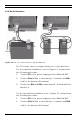
7. Pre-assembled cable set 12:
a. Connect the 2-pin plug 14 on the interface AC of the
power supply.
8. Pre-assembled cable 5:
a. Connect the loose ends of the cover tamper switch to
the 2-pin screw connector on the top of the AMC.
Position the cable in the space between the housing
and the mounting rail.
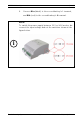
9. Connect the main AC supply X:
a. Connect the brown (phase) wire to terminal L1.
b. Connect the blue (neutral) wire to terminal N.
c. Connect the grounding cable to the housing at posi-
tion 11.
10. Connection of the extension board:
a. The extension board will be connected via the RS-485
interface of the AMC (on the left side of the tamper
contact). On the extension board itself use the same
interface.
!
DANGER!
Remove the fuse from the three-pin connector 12 before pro-
ceeding with the power supply connection.
Do not install the fuse before completing the installation proce-
dure.
!
CAUTION!
Shorten the external supply wires so that the ground (yellow/
green) wire is at least 20 mm (0.8 in.) longer than the live (blue
and brown) wires. This ensures that the ground wire cannot be
accidentally disconnected before life wires.