AMAX panel 2000 / AMAX panel 2000 EN ICP-AMAX-P / ICP-AMAX-P-EN en Installation Manual
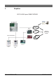
ICP-AMAX-P / ICP-AMAX-P-EN 1 3 Graphics BOSCH AMAX panel 2000 OVERVIEW ICP-AMAX-P-EN ICP-AMAX-P PSTN B420/ DX4020 TELEPHONE NETWORK IP or BOSCH OPTION BUS CENTRAL MONITORING STATION GPRS ITS-DX4020-G IP + DX3010 IUI-AMAXLCD8 IUI-AMAXLED8 Bosch Sicherheitssysteme GmbH F.01U.241.127 | V4 | 2011.
F.01U.241.127 | V4 | 2011.
AMAX panel 2000 / AMAX panel 2000 EN Table of Contents | en 5 Table of Contents 1 Short Information 10 2 System Overview 11 2.1 AMAX panel 2000 / AMAX panel 2000 EN Features 11 3 Installation 12 3.1 Quick start 12 3.1.1 Setting date and time 13 3.1.2 AMAX panel 2000 / AMAX panel 2000 EN Zone Defaults 14 3.2 System Special Status Definition 14 3.3 Programming 14 3.3.1 Programming with the AMAX Keypad 2000 14 3.3.2 Programming with the ICP-EZPK Programming key 16 3.3.
en | Table of Contents 5 AMAX panel 2000 / AMAX panel 2000 EN Fault and Tamper Description 29 5.1 Accessory Modules Fail 30 5.1.1 Keypad 1 fail 30 5.1.2 Keypad 2 fail 31 5.1.3 DX3010 Fail 31 5.1.4 B420/DX4020/ITS-DX4020G Fail 31 5.2 Power Faults 32 5.2.1 AC Failure 32 5.2.2 Battery Failure 32 5.2.3 AUX Power Supply Fail 32 5.2.4 Bosch Option Bus Power Supply Fail 33 5.2.5 RF Power Supply Fail 33 5.3 Warning Device Failure 33 5.3.
AMAX panel 2000 / AMAX panel 2000 EN Table of Contents | en 7 6.16 Add/delete User Codes 44 6.17 Add/delete Radio User Codes 44 6.18 Change Domestic Phone Number 45 6.19 Enter Programming Mode 45 6.20 Command 959 – Exit from installer’s programming mode without saving the programming data 45 6.21 Command 960 – Exit from installer’s programming mode with saving the programming data 46 6.22 Command 961 – Reset the control panel to factory default settings 46 6.
en | Table of Contents AMAX panel 2000 / AMAX panel 2000 EN 8.1.8 Zone Tamper 63 8.1.9 Zone Fault 63 8.1.10 Zone Report 63 8.1.11 Zone Chime Mode 63 8.2 System Reporting Information 63 8.2.1 System Option Programming Definition 64 8.2.2 System Report and Memory Definition 65 8.2.3 Auto Test Report 68 8.3 System Event Memory Recall 69 8.3.1 Keypad Play Back System Events 69 8.4 Output Process 69 8.4.1 Output Events Option 69 8.4.2 Output Type 72 8.4.
AMAX panel 2000 / AMAX panel 2000 EN Table of Contents | en 9 10.3.2 Remote Programming/Control 80 10.3.3 Call back Telephone Number 80 10.3.4 Exit Time 80 10.3.5 Entry Time 80 10.3.6 Keypad Lockout 81 10.3.7 Single Button STAY/AWAY ARM 81 10.3.8 Remote Arm by Software/Telephone 81 10.3.9 Arm by Keyfob 81 10.3.10 Force Arm as system is in trouble 81 10.3.11 Quick Emergency Alarm 81 10.3.12 Event Recall 81 10.3.13 OC1/Warning Device 1 Monitor 81 10.3.
1 en | Short Information AMAX panel 2000 / AMAX panel 2000 EN Short Information Congratulations on selecting the AMAX panel 2000/AMAX panel 2000 EN for your installation. Spend some time reading through this guide and familiarize yourself with the outstanding operation and installation features of this system so that you can get the most from your unit. In all aspects of planning, engineering, styling, operation, convenience and adaptability, we try to anticipate your every possible requirement.
AMAX panel 2000 / AMAX panel 2000 EN System Overview | en 2 System Overview 2.1 AMAX panel 2000 / AMAX panel 2000 EN Features 11 AMAX panel 2000/AMAX panel 2000 EN uses the latest in microprocessor technology to provide you with useful features, and superior reliability and performance.
en | Installation AMAX panel 2000 / AMAX panel 2000 EN 3 Installation 3.1 Quick start The following steps allow you to use the AMAX panel 2000/AMAX panel 2000 EN with factory default values. To become familiar with programming AMAX panel 2000/AMAX panel 2000 EN, read the information in Section 3.3 Programming, page 14. 1. Connect auxiliary equipment. 2. After all wiring is complete, connect the AC plug pack and backup battery to the control panel.
AMAX panel 2000 / AMAX panel 2000 EN Installation | en 13 3671 5 5 7 ICP-AMAX-P ICP-AMAX-P-EN 7 :( ( 3RUW 7DPSHU 6ZLWFK 3RUW 3 Z8 1 3 COM Z7 3 Z6 ,QVWDOODWLRQ &RGH 5HVWRUH 2 1 Tamper Switch 2 Zone Switch 3 EOL 2,2 k 2 COM Z5 =RQH ,&3 (=3. 3URJUDP .
en | Installation AMAX panel 2000 / AMAX panel 2000 EN Example To set the date and time for the 25th of December 2010 at 10:30PM, enter: [Installer CODE + 955][#] break until time is shown [1 0 1 2 2 5 2 2 3 0][#] 3.1.2 AMAX panel 2000 / AMAX panel 2000 EN Zone Defaults The default zone settings for the control panel are listed in Table 3.1, Page 14. You can program zones 1 to 8 to any of the zone types. Refer to Table 10.4, Page 82 for the zone type you can select.
AMAX panel 2000 / AMAX panel 2000 EN Installation | en 15 Enter the four-digit installer code (the factory default is 1234) + (958) and press [#] . Two beeps sound and the STAY and the AWAY indicators flash simultaneously to indicate that you have entered into installer’s programming mode. Once you enter into installer’s programming mode, you are automatially positioned at location 000, the first digit of the IP Address/ primary telephone number for receiver 1.
en | Installation AMAX panel 2000 / AMAX panel 2000 EN Refer to Section 3.3.3 Installer’s Programming Command, page 16 for more information about using installer’s programming mode. NOTICE! Enter command [9 5 9] [#] to exit if the setting does not need to be saved. 3.3.2 Programming with the ICP-EZPK Programming key The ICP-EZPK Programming key allows you to save or copy programming information from your control panel.
AMAX panel 2000 / AMAX panel 2000 EN 6. Installation | en 17 If the LED on the control panel PCB does not fast flash, the factory default was unsuccessful. 3.4 Prerequisites for an EN-conform Setup of the System – System must be mounted inside the monitored area on a stable surface. – Keypads must be mounted to the inner side of the monitored area. – Once the system is tested and ready to use, Enclosure Door and Keypads must be secured with screws.
en | Installation AMAX panel 2000 / AMAX panel 2000 EN Figure 3.4 5. F.01U.241.127 | V4 | 2011.12 Reassemble the Keypad (it’s now ready for use in you’re EN setup).
AMAX panel 2000 / AMAX panel 2000 EN 4 User Guide | en 19 User Guide ICP-AMAX - LED8 - 8 Zone LED Keypad ICP-AMAX-LCD8 - 8 Zone LCD Keypad Quick keypad operation instructions Arming AWAY arm [code] + [#] / [#] (quick arming) STAY arm [code] + [*] / [*] (quick arming) Disarming Disarm [code] + [#] Other Commands Fault and [code] + [2] [#] Tamper Analysis Walk test [code] + [4] [#] Event recall [code] + [5] [#] System Reset [code] + [6] [#] Bypassing zones [code] + [9] [#] [zone] + [*] [#]
en | User Guide AMAX panel 2000 / AMAX panel 2000 EN Keypad Indicators LCD keypad LED keypad indicator icons indicator lights Zone (1-8) 1 2 3 …. AWAY Status Definition on Zone is triggered. off Zone is normal. Fast flash (0.25 seconds lights on/ Zone was alarmed or is in alarm 0.25 seconds lights off) status. Slow flash (1 second lights on/1 Zone is manually bypassed or second lights off) interior Zone is in STAY ARM mode. on System is armed in AWAY mode.
AMAX panel 2000 / AMAX panel 2000 EN User Guide | en 21 Keypad sounds Sound indicator Definition One short beep A keypad button has been pressed. One single one- The requested operation is refused. Incorrect operation signal. second beep Two short beeps The system accepted the code. The system executed the requested function. One short beep In walk test mode. per second One short beep Exit time started.
en | User Guide AMAX panel 2000 / AMAX panel 2000 EN Zone description Zone 1 ______________________________________________________ Zone 2 ______________________________________________________ Zone 3 ______________________________________________________ Zone 4 ______________________________________________________ Zone 5 ______________________________________________________ Zone 6 ______________________________________________________ Zone 7 ______________________________________________________ Zo
AMAX panel 2000 / AMAX panel 2000 EN User Guide | en 23 The AWAY indicator flashes slow, and exit time starts. After exit time, the AWAY indicator is lit. Please contact your installer to enable/disable this function. Telephone remote arming The user dials the control panel number. The control panel answers the call and issues a long beep. After the long beep, the user must press the [#] key. When the Panel receives the signal it will confirm the arming of the control panel with a high tone.
en | User Guide 4.1.3 AMAX panel 2000 / AMAX panel 2000 EN Forced arming Arming the system when a zone is not sealed is known as forced arming. If the AWAY indicator does not glow, and if a long beep sounds when you attempt to arm the system in AWAY Mode, then forced arming is not permitted. If this is the case, then you will have to seal all zones or manually isolate them before you can arm the system. Please contact your installer to enable/disable this function. 4.2 Disarming the System 4.2.
AMAX panel 2000 / AMAX panel 2000 EN 5 3 25 RF Power Fault Warning Device Failure List 4 1 Warning Device 1 Disconnected 2 Warning Device 1 Short 3 Warning Device 2 Disconnected 4 Warning Device 2 Short Telephone Line Fail 5 Date and Time Fail 6 Communications failure 7 1 Communication Failure 1 2 Communication Failure 2 3 Communication Failure 3 4 Communication Failure 4 Tamper 8 4.
en | User Guide AMAX panel 2000 / AMAX panel 2000 EN Example: If the events occurred in the following order: Sequence Event 1 System armed in AWAY mode 2 Alarm in Zone 3 3 Alarm in Zone 4 4 System disarmed The alarm memory is played back in this order: Sequence Indication Event 1 All indicators off System disarmed 2 Zone 4 and AWAY indicators light Alarm in Zone 4 3 Zone 3 and AWAY indicators light Alarm in Zone 3 4 AWAY indicator lights System armed in AWAY mode Each event is
AMAX panel 2000 / AMAX panel 2000 EN 4.7.2 User Guide | en 27 Bypassing Faults and Tamper conditions (Except Zone Tampers) Bypassing Faults and Tamper conditions, one or more faults and tamper conditions are disabled for one arming cycle. After bypassing a Fault or Tamper condition, you can arm the system even when a Fault or Tamper condition exists. How to bypass faults and tamper conditions 1. Enter your user code + [97] and press [#]. Two beeps sound. 4.
en | User Guide 4.10.4 AMAX panel 2000 / AMAX panel 2000 EN Keypad medical alarm If you simultaneously press and hold [7] and [9], a silent keypad emergency medical alarm will be transmitted. Please contact your installer to enable/disable the emergency medical alarm functionality. 4.11 Domestic Dialing 4.11.1 Domestic Dialing Alarm When the control panel is activated into zone tamper/zone alarm, it can dial the mobile phone or telephone number of a family member/friend.
AMAX panel 2000 / AMAX panel 2000 EN 5 Fault and Tamper Description | en 29 Fault and Tamper Description Whenever a system fault or a tamper condition occurs, the FAULT or MAINS indicator flashes and the keypad beeps. To enter fault and tamper condition analysis mode to determine a system fault or tamper condition: 1. Enter your Code and [2] and press [#] two beeps sound.The FAULT indicator remains lit and the STAY and AWAY indicators flash.
en | Fault and Tamper Description AMAX panel 2000 / AMAX panel 2000 EN Zone Indicator 1 Accessory Modules Fail ( Refer to 5.1 ) 2 Keypad 1 fail (Refer to 5.1.1 ) 2 Keypad 2 fail (Refer to 5.1.2 ) 3 DX 3010 Fail (Refer to 5.1.3 ) 4 B420/DX 4020 /-G Fail (Refer to 5.1.4 ) Power Faults (Refer to 5.2 ) 3 1 AC Fault (Refer to 5.2.1 ) 2 Fault Battery (Refer to 5.2.2 ) 3 Aux Power Supply Fault (Refer to 5.2.3 ) 4 Bosch Option Bus Power Fault (Refer to 5.2.
AMAX panel 2000 / AMAX panel 2000 EN Fault and Tamper Description | en 1. Report the keypad fault to the configured destination programmed on location 140. 2. Flash FAULT indicator on the other keypad in normal operation (refer to the detailed 31 description in chapter keypad indicators). 3. 4.
en | Fault and Tamper Description AMAX panel 2000 / AMAX panel 2000 EN Communication with DX4020/ITS-DX4020G is normal and fault is reset. Supervise: 1. Report the DX4020/ITS-DX4020G fault to configured destination on location 140 when the fault is detected. 2. Slow flash FAULT indicator (refer to the detailed description in chapter keypad indicators) 3. When the fault is reset, send the restored report to the configured destinations.
AMAX panel 2000 / AMAX panel 2000 EN Fault and Tamper Description | en 33 Supervise: 1. Monitor the voltage by MPU. 2. Report the AUX power fault to the configured destination programmed on location 140. 3. Slow flash FAULT indicator (refer to the detailed description in chapter keypad indicators) 4. When the fault is reset, send the restored report to the configured destinations. The FAULT indicator is turned off when there is no other system fault. 5.2.
en | Fault and Tamper Description 4. AMAX panel 2000 / AMAX panel 2000 EN When the fault is reset, send the restored report to the configured destinations. The FAULT indicator is turned off when there is no other system fault. 5.3.2 Warning Device 1 Short Condition: Warning Device output is shorted. Restore: Warning Device output short is removed and fault is reset. Supervise: 1. Monitor the voltage by MPU. 2. Report the siren fault to the configured destination programmed on location 140. 3.
AMAX panel 2000 / AMAX panel 2000 EN 3. Fault and Tamper Description | en 35 Slow flash FAULT indicator (refer to the detailed description in chapter keypad indicators) 4. When the fault is reset, send the restored report to the configured destinations. The FAULT indicator is turned off when there is no other system fault 5.5 Date and Time Fail Condition: Date and time is not set after the system is powered on. Restore: Date and time is programmed and the fault is reset. Refer to Section 3.1.
en | Fault and Tamper Description AMAX panel 2000 / AMAX panel 2000 EN The fault is reset when the first kissoff tone is received and fault is reset. Supervise: 1. Report the fault to configured destination on location 140 when the fault is detected. 2. Slow flash FAULT indicator (refer the detailed description in chapter keypad indicators). 3. When the fault is reset, send the restored report to the configured destinations. The FAULT indicator is turned off when there is no other system fault.
AMAX panel 2000 / AMAX panel 2000 EN Fault and Tamper Description | en 37 The Tamper condition is reset when the Keypad is closed and Tamper condition is reset. Supervise: 1. Report the Tamper condition to configured destination on Location 140 when the Tamper Condition is detected. 2. Slow flash FAULT indicator (refer the detailed description in chapter keypad indicators). 3. When the Tamper Condition is reset, send the restored report to the configured destinations.
en | Fault and Tamper Description AMAX panel 2000 / AMAX panel 2000 EN Zone Tamper Zone Indication The zone indicator 6 lights to indicate Tamper conditions. Enter [6] to step to Zone Indicator list to identify the Tamper Zone. 1=Zone 1 2=Zone 2 3=Zone 3 4=Zone 4 5=Zone 5 6=Zone 6 7=Zone 7 8=Zone 8 5.8 External Fault Condition: Fault contact (direct connected to the Zone) is triggered (Zone type = External Fault) Restore: Fault contact is restored and Fault condition is reset. Supervise: 1.
AMAX panel 2000 / AMAX panel 2000 EN 6 System Functions | en 39 System Functions User Install Code er Function Description Code • • 0 # Duress alarm (Refer to 6.1 ) • • 1 # Siren test (Refer to 6.2 ) • • 2 # Fault and Tamper analysis (Refer to 6.3 ) • • 3 # View date and time (Refer to 6.4 ) • • 4 # Walk test (Refer to 6.5 ) • • 5 # Event memory recall (Refer to 6.6 ) • • 6 # Reset panel/clear siren (Refer to 6.7 ) • • 7 # Initiate a modem call (Refer to 6.
en | System Functions AMAX panel 2000 / AMAX panel 2000 EN A Duress Alarm is useful only if your system reports to a monitoring station, because domestic reporting format cannot define the type of alarm that occurred. 6.2 Siren Test This function allows code holders to test Sirens. Enter your Code + [1] and press [#] two beeps sound and siren's are activated for a 1~2 sec burst. No other sounding device operates during this mode. This function can only be operated as: 6.3 1. Disarm 2.
AMAX panel 2000 / AMAX panel 2000 EN 4. System Functions | en 41 If the operation is not carried out within 240 seconds after entering the walk test mode, the system will automatically exit from the setting. 6.6 Event Memory Recall Mode This function allows you to play back the last 254 system events that occurred. Event Memory Recall Mode reports all alarms and each arming or disarming of the system and helps with troubleshooting system faults. The events are shown using the keypad indicators.
en | System Functions AMAX panel 2000 / AMAX panel 2000 EN NOTICE! You can only reset Alarms Faults or Tamper conditions, when the related contact or function is idle. 6.8 Initiate a Modem Call Enter your Code + [7] and press # two beeps sound and the control panel dials the callback telephone number programmed in Location 154 – 169 in an attempt to connect to the installer’s remote computer.
AMAX panel 2000 / AMAX panel 2000 EN 1. System Functions | en 43 Enter your Code + [96] and press [#] . Two beeps sound and the STAY and AWAY indicators flash. 2. 3. Zone type for Zone 1 is shown. Refer to Section Zone Types, page 84 Press [#] to jump to Zone 2 Two beeps sound and the STAY and AWAY indicators flash. 6.12 4. Repeat this procedure to jump to the other Zones. 5.
en | System Functions AMAX panel 2000 / AMAX panel 2000 EN To set the date and time for the 25th of December 2010 at 10:30PM, enter: [1234] [955][#] break until time is shown [1 0 1 2 2 5 2 2 3 0][#] 6.16 Add/delete User Codes This function allows Installer Code holder to change or delete a User Code. 1. Enter your Installer Code +956 and press [#] . Two beeps sound and the STAY and AWAY indicators flash. 2. Enter the number of the code (1 - 8) you want to change and press [#] .
AMAX panel 2000 / AMAX panel 2000 EN System Functions | en 45 To delete a Remote Radio User Code: 1. Enter your Installer Code + 956 and press [#] . Two beeps sound and the STAY and AWAY indicators flash. 2. Enter the number of the code (9 - 16) you want to change and press [#] . Two beeps sound and the corresponding zone indicator lights. 3. Press [*] to delete the User Code. Two beeps sound and the STAY and AWAY indicators are extinguished. 4. 6.
en | System Functions 6.21 AMAX panel 2000 / AMAX panel 2000 EN Command 960 – Exit from installer’s programming mode with saving the programming data This command exits from the installer’s programming mode with saving the programming data. You can exit from installer’s programming mode from any location. Exit from installer’s programming mode: Enter [9 6 0 #] under installer’s programming mode.Two beeps sound and system resets aftersaving the programmed data and returns to the disarmed state.
AMAX panel 2000 / AMAX panel 2000 EN 6.24 System Functions | en 47 Command 963 – Copy the programming key to the control panel This command copies data from the programming key to the control panel. To copy the programming key to the control panel: 1. Enter the installer code (the default is 1234 + 958) and press [#] to enter into installer’s programming mode. Two beeps sound and the STAY and AWAY indicators flash on the remote keypad to indicate that you have entered into Installer’s Programming Mode.
en | System Informations 1 AMAX panel 2000 / AMAX panel 2000 EN 7 System Informations 1 7.1 Zone Processing when arming When the system is armed, it will do the following process. Arm precondition: The system should be disarmed. Also the system should not be in programming mode and walk test mode.
AMAX panel 2000 / AMAX panel 2000 EN System Informations 1 | en 49 Anytime the 24-Hour zone is violated. Anytime the tamper is violated. Keypad alarm operation. When system is armed and the armed zone, which is not bypassed, is violated. After the entry delay time runs out, if the system has not been disarmed and the zone has been violated, an alarm occurred. Alarm performance: Send the report to the configured destinations of the control panel system.
en | System Informations 1 AMAX panel 2000 / AMAX panel 2000 EN To program the control panel for remote connection with callback verification: 7.4.4 1. Program the Call Back Telephone Number in Location 154 – 169 . 2. Start using remote program in Location 153. Remotely Arm/Disarm System by Programming Softwares Programming softwares can be used to arm/disarm system and User Code 20 is used to send the arming/disarming reports. 7.
AMAX panel 2000 / AMAX panel 2000 EN System Informations 1 | en 51 EEE = Event Code GG = Group Number (always 0) CCC = Zone/ Contact ID, 000 is for no zone/ID message S = Checksum digit Note: Any 0 values must be sent as an 0x0A. Contact ID Report Data: 7.6.3 CFSK Format The CFSK communication format is a protocol based on the standard Bell 103 FSK (Frequency Shift Keying) modulation, as detailed by the SIA (Security Industry Associaton) “Digit Communications Standard” November 1991.
en | System Informations 1 AMAX panel 2000 / AMAX panel 2000 EN Digit Required Number to Program Digit Required Number to Program 0 0 8 8 1 1 9 9 2 2 * 11 3 3 # 12 4 4 4 sec pause 13 5 5 Terminal 15 6 6 7 7 Table 7.1 Dialing Digits To program the IP Address and port: Use no punctuation in IP address. If any unit of IP address is less than 3 digits, use 0 to fulfill the data in the higher bits. The remaining 5 digits will program the port.
AMAX panel 2000 / AMAX panel 2000 EN System Informations 1 | en 53 The pulse is used for both panel and remote receiver to know whether the network connection is good or not. Each time when a pulse is due, the control panel will send a pulse message. The pulse time range is from 1 to 999 minutes. For time less than 3 digits, use 0 to fulfill. Contact your central monitoring station for the correct setting. 7.7.3 Report Transmission Sequence (Refer to Section 10.2.
en | System Informations 1 7.7.5 AMAX panel 2000 / AMAX panel 2000 EN Receiver 1 - 4 Subscriber ID Number (Refer to Section 10.1.1 Receiver Parameters, page 78). The Subscriber ID Number is transmitted to identify the calling control panel. Enter the Subscriber ID Number in the six locations provided for each destination. Any Subscriber ID Number is less than 6 digits, use 0 to full fill the data in the higher bits. Example Program Subscriber ID Number as 4729 in six locations: [0 0 4 7 2 9] 7.7.
AMAX panel 2000 / AMAX panel 2000 EN 7.8.3 System Informations 1 | en 55 User Codes The purpose of User Codes is to arm and disarm the system and perform system functions. Refer to Section 6 System Functions, page 39. User Codes 1 to 8 can be one to four digits long. Only User Codes 9 to 16 can be used as remote radio user codes. . Use User Code 17 to send report when arming/disarming the system by key-switch.
en | System Informations 2 AMAX panel 2000 / AMAX panel 2000 EN 8 System Informations 2 8.1 General overview on zones 8.1.1 Zone Inputs On-board Inputs: There are 8 onboard hard-wired inputs for AMAX panel 2000 / AMAX panel 2000 EN. An additional input is provided for enclosure tamper but does not subtract from the 8 onboard totals.
AMAX panel 2000 / AMAX panel 2000 EN System Informations 2 | en 1650 2200 2750 normal 2970 4400 4950 trigerred 57 Using one 2.2K resistor as EOL of the tamper zone, which works together with the zone EOL 2.2K. Refer to the drawing: COM 1 2 Z3 BBBBB 7DPSHU 6ZLWFK BBBBB =RQH 6ZLWFK Figure 8.3 Dual EOL On -board Tamper Input A separate input is provided for enclosure tamper (This is in addition to the 8 on-board total inputs).
en | System Informations 2 2. AMAX panel 2000 / AMAX panel 2000 EN AWAY Arm: Zone normal - no Alarm / no report Zone triggered - Alarm / report (Zone triggered during exit time no Alarm / no report) (Zone triggered during entry time Alarm / report is delayed for 30sec or entry time is expired, when system is disarmed before, no report) 3.
AMAX panel 2000 / AMAX panel 2000 EN System Informations 2 | en 1. Disarm: same as the Instant Zone disarm status 2. AWAY Arm: same as the Delay Zone AWAY Arm status 3. 59 STAY Arm: This Zone will be Ignored and performed as disarm. Refer to Section Keypad Indicators, page 20 to see how the zone is displayed during exit time. When System is disarmed and zone is not restored before, a Zone restore report is sent 5- Follower The follower zone will perform as below: 1.
en | System Informations 2 1. AMAX panel 2000 / AMAX panel 2000 EN Disarm: Zone normal - no Alarm / no report Zone triggered - Alarm / report 2. AWAY Arm: Zone normal - no Alarm / no report Zone triggered - Alarm / report Zone triggered - during exit time - Alarm / report Zone triggered - during entry time - Alarm / report 3. STAY Arm: Same as AWAY Arm performance. A Tamper zone does not send a restore report until the zone is restored. 9- Fire Zone The Fire zone will perform as below: 1.
AMAX panel 2000 / AMAX panel 2000 EN 3. System Informations 2 | en 61 STAY Arm: Same as AWAY Arm performance. This zone is mainly for prevention of arming (to ensure exit/entry door is locked before arming the system and no alarm occurs when entering the premise through the entry/ exitdoor) 12- Key switch Toggle If a zone is programmed as key-switch toggle, it will ignore all other programming items, such as bypass, forcing arm.
en | System Informations 2 8.1.4 AMAX panel 2000 / AMAX panel 2000 EN Zone Bypass If this option is selected, the zone can be automatically isolated when the system is armed. If this option is not selected, the zone cannot be manually isolated. When a zone is manually isolated, a Zone Bypass Report is sent. When isolating 24-Hour Zone, the system automatically sends a Zone Bypass Report when the zone is seleted to be isolated. All non-24-Hour zones send a Bypass Report only when the system is armed.
AMAX panel 2000 / AMAX panel 2000 EN System Informations 2 | en 63 3. 3 Times Alarm Lockout Same as 1 time alarm lockout, but the lock out time is 3. 4. 4- 6 Times Alarm Lockout Same as 3 times alarm lockout, but the lock out time is 6. 5. Alarm Timer Lockout Repeat the process of alarm lockout, but no lockout time limits. 8.1.8 Zone Tamper The system will support the detector tamper of the zone. This will make sure the zone really works in normal status. The process is below: 1.
en | System Informations 2 8.2.1 AMAX panel 2000 / AMAX panel 2000 EN System Option Programming Definition If the system programming data is not correct, the keypad beeps to indicate wrong operation but the data is kept as the same. When the panel is starting, it will follow the Arm/disarm status before the last time the panel power was down/reset. Quick arming starts. AC MAINS Fault Report is followed with other report or one hour delayed to send out.
AMAX panel 2000 / AMAX panel 2000 EN 8.2.
en | System Informations 2 AMAX panel 2000 / AMAX panel 2000 EN Option Bus Power fail 300 1 2 0E System status • Option Bus Power 300 3 2 0F System status • RF Power fail 300 1 3 0E System status • RF Power restore 300 3 3 0F System status • Codepad fail 330 1 1,2 0E System status • Codepad fault restore 330 3 1,2 0F System status • DX3010 fail 330 1 3 0E System status • DX3010 restore 330 3 3 0F System status • DX4020/G fail 330 1 4 0E System status
AMAX panel 2000 / AMAX panel 2000 EN System Informations 2 | en 67 User code for arming/disarming report Arming/Disarming Method AWAY/STAY arming Disarming Key-switch zone User 17 (Only AWAY arming) User 17 Single button arming User 18 NA Remote telephone arming User 19 NA Remote PC arming User 20 NA Tamper Status – Tamper Report If a tamper occurs, it will send the tamper alarm report to configured destinations. Zone Status – Bypass Report A zone is bypassed when it is manually isolated.
en | System Informations 2 AMAX panel 2000 / AMAX panel 2000 EN Keypad – Medical Report A Medical Report is sent to the base station destination when a user presses [7] and [9] at the same time.Restore Reports are not sent for this event. System Status – AUX Power Supply Fail Report A System Fault Report is sent when the AUX Power Supply is fail.
AMAX panel 2000 / AMAX panel 2000 EN 8.3 System Informations 2 | en 69 System Event Memory Recall There are two Event Memorys, one for ALL EVENTS and one for EN EVENTS. Up to 254 system events can be recorded in event memory in chronological order. These events are with date and time information and stored in non-volatile memory. For Event records refer toTable 8.1, Page 66. 8.3.
en | System Informations 2 AMAX panel 2000 / AMAX panel 2000 EN The output is reset: 1. When the system is disarmed 2. When the output programmed duration is up. If this duration is programmed as 000, the output will continue till the system disarmed. 3 – System Alarm This output operates when an alarm occurs. The output is reset: 1. When the system is disarmed and alarm is reset. 2. When the output programmed duration is up. When a new alarm occurred, the alarm will reset the alarm time.
AMAX panel 2000 / AMAX panel 2000 EN 1. System Informations 2 | en 71 Only after a Dynamic Battery Test report that the backup battery voltage is normal and fault is reset. 2. When the output programmed duration is up. If this duration is programmed as 000, the output will continue till the AC MAINS power is restored. 8 – RF Power Fault This output operates when RF power is lost. The output is reset: 1. When the output programmed duration is up. 2.
en | System Informations 2 AMAX panel 2000 / AMAX panel 2000 EN When a new alarm occurred, the alarm will reset the alarm time. 15 – Reset This output operates when a reset is performed in the system. 8.4.2 Output Type The outputs have two kinds of type: 0 – Steady Output The polarity is stable low electrical level output. 1 – Pulse Output The polarity is pulse output. 8.4.3 Output Duration Each output duration can be programmed. The output duration is based on each Event.
AMAX panel 2000 / AMAX panel 2000 EN 8.5.2 System Informations 2 | en 73 Exit Time You can program Exit Time from 0 to 255 sec in increments of 1 sec. When arming the system in AWAY Mode, the remote keypad beeps during Exit Time until the final 10 sec, when the keypad sounds one continuous beep to indicate the end of Exit Time is near. 8.5.
en | System Informations 2 AMAX panel 2000 / AMAX panel 2000 EN Figure 8.4 DX3010 Location Setting 8.6.6 B420/DX4020/ITS-DX4020G GSM GPRS Communication Module The AMAX panel 2000 / AMAX panel 2000 EN Control Panel supports one B420 or one DX4020 network communication module or ITS-DX4020G GSM/GPRS communication module. Only one can be selected to connect in one system to send reports thought the network. Set in Location 134 to use B420/DX4020/ITS-DX4020G as below: Figure 8.
AMAX panel 2000 / AMAX panel 2000 EN 9 Technical Data 9.
en | Technical Data AMAX panel 2000 / AMAX panel 2000 EN Aux (+12V/GND) Output: – Nominal Output Voltage under AC line input: 13,5 VDC +3% / -5% – Output Voltage Range under AC line input: 12,82 VDC to 13,9 VDC Option Bus: – 500mA maximum – Vpp (max) 675mV – Nominal Output Voltage under AC line input: 13,5 VDC +3% / -5% – Output Voltage Range under AC line input: 12,82 VDC to 13,9 VDC – 500mA maximum RF Power Output – 5VDC / 100mA maximum Panel PCB – Quiescent current maximum 100m
AMAX panel 2000 / AMAX panel 2000 EN Technical Data | en 9.2 Interface Description 9.2.1 Terminals Internal Description Terminal 77 Description These two terminals are the plug-on type and are the terminal points for the 18 VAC transformer. To ensure correct operation, the voltage of the transformer must be 18 VAC to 22VAC at 1.
en | Programming sheets AMAX panel 2000 / AMAX panel 2000 EN 10 Programming sheets 10.1 Receiver Programming 10.1.
AMAX panel 2000 / AMAX panel 2000 EN Programming sheets | en 79 Example: For IP Address for receiver 128.73.168.7, communication port 7700, program as: 128 073 168 007 07700 NOTICE! Programming option anti-replay, acknowledge wait time and pulse interval time are only used in Bosch network format. 10.1.2 10.
en | Programming sheets AMAX panel 2000 / AMAX panel 2000 EN Zone Status Reporting Options 5 Report to Receiver 1,2,3,4 6 Report to destination 1 (2,3,4 backup) 7 Report to destination 1 (2 backup) and destination 3 (4 backup) NOTICE! The system sends no report when programmed to report to the receiver as Option 0. 10.2.
AMAX panel 2000 / AMAX panel 2000 EN 10.3.6 Programming sheets | en 81 Keypad Lockout Location 179 Location Default 1 - 15= attempt times 0=no lockout 179 6 EN=10 If an invalid code attempts more times than programmed, the keypad is locked out for 3 minutes. 10.3.7 10.3.8 10.3.9 10.3.10 10.3.11 10.3.12 10.3.13 10.3.14 10.3.
en | Programming sheets 10.3.16 10.3.17 10.3.18 10.3.19 10.
AMAX panel 2000 / AMAX panel 2000 EN Programming sheets | en Reserved 228-229 0 Zone Type (Refer to zone type option) 230 1 Zone Bypass (Disable=0, Enable=1) 231 1 Forced Arming (Disable=0, Enable=1) 232 1 EN=0 Silent Alarm (Enable=1, Disable=0) 233 0 EN=0 Zone alarm lock out time (disable=0, 1 times=1, 3 times=2, 6 234 0 EN=4 Support Detector Tamper (Disable=0, Enable=1) 235 1 Zone alarm report (Refer to zone report option) 236 6 EN=1/5/ 83 Zone #03 times=3, alarm duration=4) 6
en | Programming sheets AMAX panel 2000 / AMAX panel 2000 EN Silent Alarm (Enable=1, Disable=0) 263 0 EN=0 Zone alarm lock out time (disable=0, 1 times=1, 3 times=2, 6 264 0 Support Detector Tamper (Disable=0, Enable=1) 265 1 Zone alarm report (Refer to zone report option) 266 6 EN=1/5/ times=3, alarm duration=4) 6/7 Zone Chime Mode (Enable=1, Disable=0) 267 0 Reserved 268-269 0 Zone Type (Refer to zone type option) 270 1 Zone Bypass (Disable=0, Enable=1) 271 1 Forced Arming
AMAX panel 2000 / AMAX panel 2000 EN Programming sheets | en Zone Type Description 7 24-Hour 8 Tamper 9 Fire 10 External Fault 11 Bolt Contact 12 Key Switch Toggle 13 Key Switch on/off 10.5 Output Programming 10.5.1 Keypad Buzzer 10.5.
en | Programming sheets AMAX panel 2000 / AMAX panel 2000 EN Polarity Mode (0=Steady, 1=Pulse) 386 0 Output Duration (001-999sec/000=on) 387-389 030 Event Type (Refer to output events option) 390 0 Polarity Mode (0=Steady, 1=Pulse) 391 0 Output Duration (001-999sec/000=on) 392-394 030 Relay Output 2 Relay Output 3 Event Type (Refer to output events option) 395 0 Polarity Mode (0=Steady, 1=Pulse) 396 0 Output Duration (001-999sec/000=on) 397-399 030 Event Type (Refer to output
AMAX panel 2000 / AMAX panel 2000 EN Event Type Description 0 No output activate for the events 1 System Disarmed 2 System Armed 3 System Alarm 4 Entry/Exit Delay Warning 5 Telephone Line Fail 6 AC Lost 7 Battery Low 8 RF Power Fault 9 TAMPER 10 External Fault 11 All Faults 12 Away armed 13 Stay armed 14 Reset 15 24h Alarm Table 10.1 10.
en | Programming sheets AMAX panel 2000 / AMAX panel 2000 EN User #07 460-464 15 User #08 465-469 15 RF User #09 470-474 15 EN=15 RF User #10 475-479 15 EN=15 RF User #11 480-484 15 EN=15 RF User #12 485-489 15 EN=15 RF User #13 490-494 15 EN=15 RF User #14 495-499 15 EN=15 RF User #15 500-504 15 EN=15 RF User #16 505-509 15 EN=15 F.01U.241.127 | V4 | 2011.
AMAX panel 2000 / AMAX panel 2000 EN 11 Troubleshooting | en 89 Troubleshooting Trouble Causes & Measures No immediate response – from zone testing right To work normally, operate the system one minute after powered up. after powered up. No indication on keypad – Check that the AC Mains power and battery fuse are – Check the Bosch Bus RBGY are correctly connected. No response from the – Check the Bosch Bus RBGY are correctly connected.
en | Troubleshooting AMAX panel 2000 / AMAX panel 2000 EN Trouble Causes & Measures Battery fault still – System test the battery each time arming or every time set in location 191. Only after testing the battery fault can be indicates after replaced cleared away. with new battery. – Voltage of the new battery reaches the normal value after it is charged for some time. Control Panel does not – dial.
Bosch Sicherheitssysteme GmbH Robert-Bosch-Ring 5 85630 Grasbrunn Germany www.boschsecurity.