Customer: Location: Account #: Installer: Date: AMAX panel 2000 / AMAX panel 2000 EN F.01U.241.
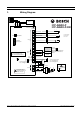
F.01U.241.128 3 1 Wiring Diagram 3671 5 5 7 ICP-AMAX-P ICP-AMAX-P-EN 7 :( ( 3RUW 7DPSHU 6ZLWFK 3RUW 3 Z8 1 3 COM Z7 3 Z6 ,QVWDOODWLRQ &RGH 5HVWRUH 2 1 Tamper Switch 2 Zone Switch 3 EOL 2,2 k 2 COM Z5 =RQH ,&3 (=3. 3URJUDP .
F.01U.241.128 | V2 | 2011.11 F.01U.241.
AMAX panel 2000 / AMAX panel 2000 EN Table of Contents | en 5 Table of Contents 1 Summary 7 1.1 Introduction 7 1.2 Installation 7 1.3 Programming 7 1.4 Quick start 7 1.5 Using the keyboard for programming 8 1.6 Setting date and time 9 1.7 System installer password reset 9 2 User and Installer Code Functions 10 3 Fault and Tamper Description 11 4 Programming sheets 13 4.1 Receiver programming 13 4.1.1 Receiver parameters 13 4.1.2 Domestic programming 14 4.
en | Table of Contents AMAX panel 2000 / AMAX panel 2000 EN 4.5.5 DX3010 Output 20 4.6 Installer/User Code Programming 22 4.6.1 Installer code #0 22 4.6.2 User Codes 22 5 Specification 24 6 FAQs 26 Glossary 28 Index 29 F.01U.241.128 | V2 | 2011.
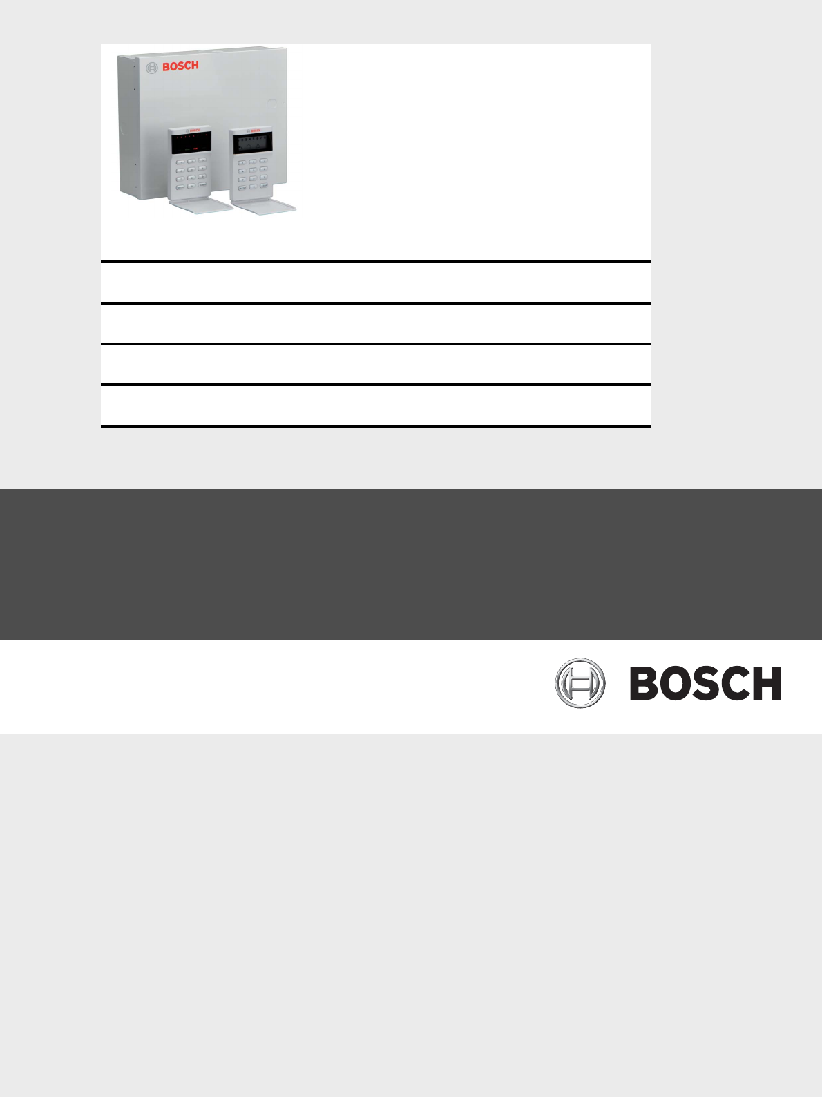
AMAX panel 2000 / AMAX panel 2000 EN 1 Summary 1.1 Introduction Summary | en 7 Thank you for choosing the AMAX Panel 2000/ AMAX Panel 2000 EN alarm host. This is a flexible, reliable, convenien, and easy-to-use alarm system. This Quick reference guide is provided with the system to give basic information about the basic system wiring, components, and programming. As the system includes a large number of programmable functions and options, we suggest reading the complete installation instructions.
en | Summary AMAX panel 2000 / AMAX panel 2000 EN 9. 1.5 Enter the default user code (2580) and (6) and press [#] to reset the panel. Using the keyboard for programming The system must be disarmed (no alarms) for programming. If there are alarms or the system is armed, please enter the user code for user code 1 (confirmation 2580), then press the [#] key (user code 1 is the factory preset user).
AMAX panel 2000 / AMAX panel 2000 EN Summary | en 9 Keyboard indicator light Date Area 1 Area 2 Area 3 Area 4 Area 5 Area 6 Area 7 Area 8 Power Value indicat indicat indicat indicat indicat indicat indicat indicat source or light or light or light or light or light or light or light or light indicator light 0 1 X 2 X 3 X 4 X 5 X 6 X 7 X 8 9 X X X 10 11 X X 12 X X 13 X X 14 X X 15 1.
2 en | User and Installer Code Functions AMAX panel 2000 / AMAX panel 2000 EN User and Installer Code Functions User Install Code er Function Description Code • • 0 # Duress alarm • • 1 # Siren test • • 2 # Fault and Tamper analysis • • 3 # View date and time • • 4 # Walk test • • 5 # Event memory recall • • 6 # Reset panel/clear siren • • 7 # Initiate a modem call • • 8 # Send Test report • • 9 # Bypass (inhibit) • • 96 # Show Zone type •
AMAX panel 2000 / AMAX panel 2000 EN 3 Fault and Tamper Description | en 11 Fault and Tamper Description Whenever a system fault or a tamper condition occurs, the FAULT or MAINS indicator flashes and the keypad beeps. To enter fault and tamper condition analysis mode to determine a system fault or tamper condition: 1. Enter your Code and [2] and press [#] two beeps sound.The FAULT indicator remains lit and the STAY and AWAY indicators flash.
en | Fault and Tamper Description AMAX panel 2000 / AMAX panel 2000 EN Zone Indicator 1 2 3 Accessory Modules Fail 1 Keypad 1 fail 2 Keypad 2 fail 3 DX 3010 Fail 4 B420/DX 4020 /-G Fail Power Faults 1 AC Fault 2 Fault Battery 3 Aux Power Supply Fault 4 Bosch Option Bus Power Fault 5 RF Power Fault Warning Device Failure List 1 Warning Device 1 Disconnected 2 Warning Device 1 Short 3 Warning Device 2 Disconnected 4 Warning Device 2 Short 4 Telephone Line Fail 5 Date and
AMAX panel 2000 / AMAX panel 2000 EN 4 Programming sheets 4.1 Receiver programming 4.1.
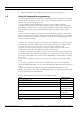
en | Programming sheets AMAX panel 2000 / AMAX panel 2000 EN Example: For IP Address for receiver 128.73.168.7, communication port 7700, program as: 128 073 168 007 07700 NOTICE! Programming option anti-replay, acknowledge wait time and pulse interval time are only used in Bosch network format. 4.1.2 4.
AMAX panel 2000 / AMAX panel 2000 EN Programming sheets | en 15 Zone Status Reporting Options 5 Report to Receiver 1,2,3,4 6 Report to destination 1 (2,3,4 backup) 7 Report to destination 1 (2 backup) and destination 3 (4 backup) NOTICE! The system sends no report when programmed to report to the receiver as Option 0. 4.2.
en | Programming sheets 4.3.6 AMAX panel 2000 / AMAX panel 2000 EN Keypad Lockout Location 179 Location Default 1 - 15= attempt times 0=no lockout 179 6 EN=10 If an invalid code attempts more times than programmed, the keypad is locked out for 3 minutes. 4.3.7 4.3.8 4.3.9 4.3.10 4.3.11 4.3.12 4.3.13 4.3.14 4.3.
AMAX panel 2000 / AMAX panel 2000 EN 4.3.16 4.3.17 4.3.18 4.3.19 4.
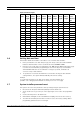
en | Programming sheets AMAX panel 2000 / AMAX panel 2000 EN Zone #03 Zone Type (Refer to zone type option) 230 1 Zone Bypass (Disable=0, Enable=1) 231 1 Forced Arming (Disable=0, Enable=1) 232 1 EN=0 Silent Alarm (Enable=1, Disable=0) 233 0 EN=0 Zone alarm lock out time (disable=0, 1 times=1, 3 times=2, 6 234 0 EN=4 Support Detector Tamper (Disable=0, Enable=1) 235 1 Zone alarm report (Refer to zone report option) 236 6 EN=1/ times=3, alarm duration=4) 5/6/7 Zone Chime Mode (Ena
AMAX panel 2000 / AMAX panel 2000 EN Programming sheets | en Zone alarm report (Refer to zone report option) 266 19 6 EN=1/ 5/6/7 Zone Chime Mode (Enable=1, Disable=0) 267 0 Reserved 268-269 0 Zone Type (Refer to zone type option) 270 1 Zone Bypass (Disable=0, Enable=1) 271 1 Forced Arming (Disable=0, Eanble=1) 272 1 EN=0 Silent Alarm (Enable=1, Disable=0) 273 0 EN=0 Zone alarm lock out time (disable=0, 1 times=1, 3 times=2, 6 274 0 Support Detector Tamper (Disable=0, Enable=1) 2
en | Programming sheets AMAX panel 2000 / AMAX panel 2000 EN Zone Type Description 12 Key Switch Toggle 13 Key Switch on/off 4.5 Output Programming 4.5.1 Keypad Buzzer 4.5.
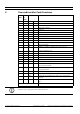
AMAX panel 2000 / AMAX panel 2000 EN Programming sheets | en 21 Relay Output 3 Event Type (Refer to output events option) 395 0 Polarity Mode (0=Steady, 1=Pulse) 396 0 Output Duration (001-999sec/000=on) 397-399 030 Event Type (Refer to output events option) 400 0 Polarity Mode (0=Steady, 1=Pulse) 401 0 Output Duration (001-999sec/000=on) 402-404 030 Event Type (Refer to output events option) 405 0 Polarity Mode (0=Steady, 1=Pulse) 406 0 Output Duration (001-999sec/000=on) 407-40
en | Programming sheets Event Type Description 0 No output activate for the events 1 System Disarmed 2 System Armed 3 System Alarm 4 Entry/Exit Delay Warning 5 Telephone Line Fail 6 AC Lost 7 Battery Low 8 RF Power Fault 9 TAMPER 10 External Fault 11 All Faults 12 Away armed 13 Stay armed 14 Reset 15 24h Alarm Table 4.1 4.
AMAX panel 2000 / AMAX panel 2000 EN 4.6.
5 en | Specification AMAX panel 2000 / AMAX panel 2000 EN Specification Panel Enclosure : Dimensions (HxWxD): – Weight: – 260mm x 280mm x 83,5mm 1950g Environmental Considerations: Relative Humidity: – 10%-95% Operating Temperature: – -10°C - +55°C Supervised Zones: Onboard: Z1 - Z8 COM – 8 Single or dual end-of-line (EOL 2,2KΩ) tamper point support P8 Tamper – Enclosure tamper input (does not reduce point capacity) Programmable Outputs (PO): Onboard: OC 1 – supervised output max 5
AMAX panel 2000 / AMAX panel 2000 EN Specification | en – 25 Output Voltage Range under AC line input: 12,82 VDC to 13,9 VDC Option Bus: – 500mA maximum – Vpp (max) 675mV – Nominal Output Voltage under AC line input: 13,5 VDC +3% / -5% – Output Voltage Range under AC line input: 12,82 VDC to 13,9 VDC – 500mA maximum RF Power Output – 5VDC / 100mA maximum Panel PCB – Quiescent current maximum 100mA Battery: – D126 (12V/7 Ah) sealed, lead acid rechargeable – Low battery condition is
6 en | FAQs AMAX panel 2000 / AMAX panel 2000 EN FAQs Issues Causes and solutions After turning on the – In order to ensure regular operation, after power is turned on, the system needs to stabilize for one minute unit, there is no response for a defense zone monitor for a short time. After turning the unit – Check whether the AC power supply and battery fuse are working correctly on, the keyboard does not show.
AMAX panel 2000 / AMAX panel 2000 EN After an auxiliary FAQs | en – 27 Restart the AC power supply and battery power source short circuit, system cannot be restored. After changing the – is cleared still shows.
en | Glossary AMAX panel 2000 / AMAX panel 2000 EN Glossary A Alarm Event that is configured as an alarm. This is a particular situation (motion detected, doorbell rung, signal lost, etc.) that requires immediate attention. An alarm can include live video, playback video, an action plan, or a map. F.01U.241.128 | V2 | 2011.
AMAX panel 2000 / AMAX panel 2000 EN Index | en 29 Index Robert Bosch Engineering and Business Solutions LimitedQuick Reference Guide F.01U.241.128 | V2 | 2011.
en | Index F.01U.241.128 | V2 | 2011.
Robert Bosch Engineering and Business Solutions Limited 123, Industrial Layout, Hosur Road 560095 Banglore India www.bosch.