
Data Sheet
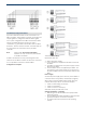


Table Of Contents

2 | AMC2 - Input/Output Extension Boards
Installation/Configuration Notes
Up to three extension boards can be connected to one
AMC2 controller; this provides a maximum of 56 input and
output signals for configuration with the AMC2 signals.
For a system configuration the AMC2 16I-16O-EXT, AMC2
16I-EXT, and AMC2 8I-8O-EXT can also be used in
combination, e.g. two AMC2 16I-16O-EXTs and one AMC2
8I-8O-EXT – but the maximum number of modules that can
be connected is also restricted to three per AMC2
controller.
Note Systems with Access Personal Edition
Software can only connect one I/O-Extension
to an AMC2 Controller.
An AMC2 16I-16O-EXT can only provide signals for the
entrances of the AMC2 controller to which it is connected.
It is not possible to transmit to another AMC2.
Configuration examples:
Solid lines: Power supply
Dotted lines: Data lines
1. AMC2 with power supply.
2. Power and data are supplied to the AMC2 xxx-EXT via
the AMC2.
3. The AMC2 xxx-EXT with its own power supply receives
data from the AMC2.
4. The first AMC2 xxx-EXT is supplied by the AMC2 - the
second has its own power supply and a connection to
the third. All AMC2 xxx-EXTs receive their data from the
AMC2.
Power supply
An external power supply (10 to 30 V DC) for the AMC2 is
connected to the first (positive) and third pin (negative).
When using an uninterruptible power supply (UPS), the
relevant UPS output relay is connected to the pins
•
4 and 7 for alternating current (AC)
•
5 and 7 for the battery
•
6 and 7 for direct current (DC)
Otherwise, these pins will short-circuit.
Voltage equalization - grounding
•
Different grounds can be balanced via jumpers with
protective ground.
•
A line (shielding, potential equalization) with protective
ground must only be connected in one place.
•
For further instructions, please see the operating
manual.