LTC 9385 Series Instruction Manual EN Outdoor Housings
LTC 9385 Series | Instruction Manual | Important Safeguards EN | 2 Important Safeguards 1. Read, Follow, and Retain Instructions - All safety and operating instructions should be read and followed before operating the unit. Retain instructions for future reference. 2. Heed Warnings - Adhere to all warnings on the unit and in the operating instructions. 3. Attachments - Attachments not recommended by the product manufacturer should not be used, as they may cause hazards. 4.
EN | 3 LTC 9385 Series | Instruction Manual | Safety Precautions For Indoor Product 1. Water and Moisture - Do not use this unit near water - for example, in a wet basement, in an unprotected outdoor installation or in any area classified as a wet location. 2. Object and Liquid Entry - Never push objects of any kind into this unit through openings, as they may touch dangerous voltage points or short out parts that could result in a fire or electrical shock. Never spill liquid of any kind on the unit. 3.
EN | 4 LTC 9385 Series | Instruction Manual | Safety Precautions Sicherheitshinweise VORSICHT: UM EINEN ELEKTRISCHEN SCHLAG ZU VERMEIDEN, IST DIE ABDECKUNG (ODER RÜCKSEITE) NICHT ZU ENTFERNEN. ES BEFINDEN SICH KEINE TEILE IN DIESEM BEREICH, DIE VOM BENUTZER GEWARTET WERDEN KÖNNEN. LASSEN SIE WARTUNGSARBEITEN NUR VON QUALIFIZIERTEM WARTUNGSPERSONAL AUSFÜHREN. Das Symbol macht auf nicht isolierte „gefährliche Spannung" im Gehäuse aufmerksam. Dies kann zu einem elektrischen Schlag führen.
EN | 5 LTC 9385 Series | Instruction Manual | Safety Precautions Medidas de Segurança CUIDADO: PARA REDUZIR O RISCO DE CHOQUE ELÉCTRICO, NÃO RETIRE A TAMPA (OU A PARTE POSTERIOR). NO INTERIOR, NÃO EXISTEM PEÇAS QUE POSSAM SER REPARADAS PELO UTILIZADOR. REMETA A ASSISTÊNCIA PARA OS TÉCNICOS QUALIFICADOS. Este símbolo indica a presença de "tensão perigosa" não isolada dentro da estrutura do produto, o que pode constituir risco de choque eléctrico.
LTC 9385 Series | Instruction Manual | Contents EN | 6 Table of Contents Important Safeguards . . . . . . . . . . . . . . . . . . . . . . . . . . . . . . . . . . . . . . . . . . . . . . . . . . . . . . . . . . . . . . . . . . . . . .2 1.0 UNPACKING . . . . . . . . . . . . . . . . . . . . . . . . . . . . . . . . . . . . . . . . . . . . . . . . . . . . . . . . . . . . . . . . . . . . . .7 2.0 SERVICE . . . . . . . . . . . . . . . . . . . . . . . . . . . . . . . . . . . . . . . . . . . . . . . . . . . . . .
EN | 7 LTC 9385 Series | Instruction Manual | Unpacking 1.0 UNPACKING This electronic equipment should be unpacked and handled carefully. Check for the following items: Quantity Part Description 1 1/4-20 x 3/8in. BHCS (Button Head Cap Screw) 1 1/4-20 x 1/2in. BHCS 1 1/4-20 x 5/8in. BHCS 1 1/4-20 x 3/4in. BHCS 1 1/4-20 x 7/8in. BHCS 4 3.2mm (0.125in.) plastic spacer 4 0.4mm (0.016in.) plastic spacer 2 Nylon bushings 1 3/8in.
EN | 8 LTC 9385 Series | Instruction Manual | Installation 5.2 • • • • • • • • 5.3 • • • 5.4 Input Power Cord - European Tools Required Flat blade screwdriver Phillips head screwdriver M7 (7mm) hex wrench or socket M3 (3mm) hex wrench M4 (4mm or 5/32in.) hex wrench M8 (8mm or 5/16in.) hex wrench Adjustable wrench Wire cutter/stripper/crimper tool Cable Type H05RN-F3G0.75 and H05RN-F3G1.00 Cable Size Outside diameter between 4.3mm and 11.9mm (0.170in. and 0.470in.
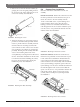
EN | 9 LTC 9385 Series | Instruction Manual | Installation 3. Remove the cover from the base assembly by grasping the cover and gently pulling forward. Do not remove the safety cable from the cover or the base assembly. See FIGURE 2. Cover 5.6 Camera/Lens Installation Place the camera/lens combination onto the rail assembly. Fixed Lens Cameras: Position the camera/lens so that the lens is positioned over the heater but not past it. Secure the camera to the rail assembly with the 1/4-20 x 3/8in.
EN | 10 LTC 9385 Series | Instruction Manual | Installation 5.7 Camera/Lens Wiring 5.8 WARNING: Only use the cables specified under INSTALLATION, Cable Requirements for wiring of all cameras and lenses. If no lens control or feed-through wiring will be used, install the 3/8in. NPT plug provided. Remove the liquid-tight fitting and insert the plug in the small bottom center 3/8in. NPT hole. Use a 8mm or a 5/16in. hex wrench to tighten securely.
EN | 11 LTC 9385 Series | Instruction Manual | Installation Recommended Maximum Cable Lengths Models Wire Size Distance mm2 1.5 2.5 4 AWG 16 14 12 -2 (24 VAC) 0.5 0.5 1 1.5 2.5 22 20 18 16 14 10 15 25 40 70 30 50 80 120 210 -4 (230 VAC) 1.5 2.5 4 16 14 12 4000 6400 10000 13000 21000 32800 -1 (115 VAC) meters 1000 1600 2500 feet 3280 5250 8200 1. Use the liquid-tight fitting on the left of the housing to route the power supply cord into the housing. 2.
EN | 12 LTC 9385 Series | Instruction Manual | Installation LTC 9385/20 Housings These housings are to be connected to 24VAC, and are designed for use where site power is 24volts. The LTC 9385/20 housings should only be used with 24volt cameras. The integral heater/defogger requires 24volts. The housing is shipped with the heater/ defogger connected to the terminal block.
EN | 13 LTC 9385 Series | Instruction Manual | Installation BNC Connector Video Coax Cable CCD Camera 5.11 Small Fitting Video Coax Cable CCD Camera BNC Connector Small Fitting FIGURE 11 Video Coax Connection 5.10 If using a pan/tilt with a feed-through cable, insert the camera/lens function cable in through the right fitting at the rear of the cradle. Wire the functions as described above, or as needed.
EN | 14 LTC 9385 Series | Instruction Manual | Installation 5.13 Final Assembly 5.13.1 Pull Seal Installation If the breather hole is open, do NOT mount the housing in a position where the front face plate is pointed upward. To maintain enclosure protection ratings of NEMA-4 and IP65, the pull seal (provided in the hardware kit) must be installed in the front face plate. It is recommended that the pull seal be installed in a cool, dry environment to prevent trapping moisture inside the housing.
EN | 15 LTC 9385 Series | Instruction Manual | Installation 5.13.2 Housing Assembly 1. The lens support screw is provided to support the rail assembly. Adjustment will only be necessary if the rail assembly is rotated at angle other than horizontal. If the screw head is not touching the cover when the cover is installed, loosen the screw until it does. See FIGURE 18. 3. Align the cover holes with the base assembly holes and replace the two M4 screws and washers.
EN | 16 LTC 9385 Series | Instruction Manual | Exploded View 6.0 EXPLODED VIEW FIGURE 21 7.0 PARTS LIST Ref Drawing No. No. Qty.