AutoDome Junior HD VJR Series en Installation Manual
AutoDome Junior HD Table of Contents | en 3 Table of Contents 1 Safety 8 1.1 Important Safety Instructions 8 1.2 Safety Precautions 11 1.3 Important Notices 11 1.4 Customer Support and Service 18 2 Unpacking 19 2.1 Parts List 19 2.2 Safety Rules 20 2.3 Installation Notes 20 3 Description 21 4 Installing a Surface Mount 23 4.1 Description 23 4.1.1 Additional Tools Required 24 4.1.2 Preparing the Surface Mount for an Indoor Installation 24 4.1.
en | Table of Contents AutoDome Junior HD 6 Installing a Recessed Mount 46 6.1 Description 46 6.2 Indoor Recessed Installation 47 6.2.1 Additional Requirements 47 6.2.2 Preparing the Ceiling for Installation 48 6.2.3 Installing the Camera to the Mounting Plate 51 6.3 Outdoor and IP54 Recessed Installation 55 6.3.1 Installation Requirements 56 6.3.2 Preparing the Ceiling for Installation 56 6.3.
AutoDome Junior HD Table of Contents | en 5 11 Using the IP Interface 88 11.1 Overview of Features 89 11.2 System Requirements 90 11.3 Connecting the AutoDome Junior HD to the PC 91 11.4 Configuring the AutoDome Junior HD Camera 92 11.4.1 Changing the Network Settings 93 11.5 The Livepage 95 11.5.1 Entering a Keyboard Control Command 100 11.5.2 Using Special Functions 102 11.6 Commissioning the AutoDome Junior Fixed Camera 103 11.7 Saving Snapshots 104 11.
en | Table of Contents AutoDome Junior HD 12.22 PTZ Settings 137 12.23 Diagnostics 138 12.24 Preposition and Tours 139 12.25 Sectors 140 12.26 Miscellaneous 141 12.27 Logs 141 12.28 Audio 141 12.29 Pixel Counter 142 12.30 Advanced Mode: Recording 142 12.31 Storage Management 142 12.32 Recording Profiles 145 12.33 Retention Time 148 12.34 Recording Schedule 148 12.35 Recording Status 150 12.36 Advanced Mode: Alarm 150 12.37 Alarm Connections 150 12.
AutoDome Junior HD Table of Contents | en 7 13 Keyboard Commands by Number 179 14 Preventive Maintenance 181 15 Troubleshooting 182 15.1 AutoDome Junior Operation and Control 182 15.2 LED Diagnostics 184 16 BVIP Firmware Updates 185 16.1 Upgrading the AutoDome Junior IP or HD 185 16.2 Beginning the Firmware Update Process 186 Index 187 Bosch Security Systems, Inc. Installation Manual F.01U.275.803 | 6.0 | 2012.
en | Safety AutoDome Junior HD 1 Safety 1.1 Important Safety Instructions Read, follow, and retain for future reference all of the following safety instructions. Heed all warnings on the unit and in the operating instructions before operating the unit. 1. Cleaning - Unplug the unit from the outlet before cleaning. Follow any instructions provided with the unit. It is generally sufficient to use a dry cloth for cleaning, but a moist lint-free cloth or leather shammy may also be used.
AutoDome Junior HD 7. Safety | en 9 Control adjustment - Adjust only those controls specified in the operating instructions. Improper adjustment of other controls may cause damage to the unit. Use of controls or adjustments, or performance of procedures other than those specified, may result in hazardous radiation exposure. 8. Overloading - Do not overload outlets and extension cords. This can cause fire or electrical shock. 9.
en | Safety AutoDome Junior HD 11. Servicing - Do not attempt to service this unit yourself. Opening or removing covers may expose you to dangerous voltage or other hazards. Refer all servicing to qualified service personnel. 12.
AutoDome Junior HD 1.2 Safety | en 11 Safety Precautions DANGER! This symbol indicates an imminently hazardous situation such as “Dangerous Voltage” inside the product. If not avoided, this will result in an electrical shock, serious bodily injury, or death. WARNING! Indicates a potentially hazardous situation. If not avoided, this may result in minor or moderate injury. Alerts the user to important instructions accompanying the unit. CAUTION! Indicates a potentially hazardous situation.
en | Safety AutoDome Junior HD switch as the main disconnect device for switching off the voltage to the unit. Camera grounding - When mounting the camera in potentially damp environments, ensure the system is grounded through the metal housing of the unit (see section: Connecting the Power). Camera signal - Protect the cable with a primary protector if the camera signal is over 140 feet, in accordance with NEC800 (CEC Section 60).
AutoDome Junior HD Safety | en 13 Environmental statement - Bosch has a strong commitment to the environment. This unit has been designed to respect the environment as much as possible. Electrostatic-sensitive device - Take proper CMOS/MOS-FET handling precautions to avoid electrostatic discharge. NOTE: You must wear grounded wrist straps and observe proper ESD safety precautions when handling the electrostaticsensitive printed circuit boards.
en | Safety AutoDome Junior HD Power disconnect - Units have power supplied whenever the power cord is inserted into the power source. The power cord is the main power disconnect for all units. Power lines - Do not locate the camera near overhead power lines, power circuits, electrical lights, or anywhere where it might come into contact with power lines, circuits, or lights. SELV All the input/output ports are Safety Extra Low Voltage (SELV) circuits.
AutoDome Junior HD Safety | en 15 FCC & ICES INFORMATION (U.S.A. and Canadian Models Only) This device complies with part 15 of the FCC Rules. Operation is subject to the following conditions: – this device may not cause harmful interference, and – this device must accept any interference received, including interference that may cause undesired operation.
en | Safety AutoDome Junior HD INFORMATIONS FCC ET ICES (modèles utilisés aux États-Unis et au Canada uniquement) Ce produit est conforme aux normes FCC partie 15. La mise en service est soumises aux deux conditions suivantes: – cet appareil ne peut pas provoquer d'interférence nuisible et – cet appareil doit pouvoir tolérer toutes les interférences auxquelles il est soumit, y compris les interférences qui pourraient influer sur son bon fonctionnement.
AutoDome Junior HD Safety | en 17 Disclaimer Underwriter Laboratories Inc. (“UL”) has not tested the performance or reliability of the security or signaling aspects of this product. UL has only tested fire, shock and/or casualty hazards as outlined in UL's Standard(s) for Safety for Information Technology Equipment, UL/IEC 60950-1. UL Certification does not cover the performance or reliability of the security or signaling aspects of this product.
en | Safety 1.4 AutoDome Junior HD Customer Support and Service If this unit needs service, contact the nearest Bosch Security Systems Service Center for authorization to return and shipping instructions. Service Centers USA Repair Center Telephone: 800-566-2283 Fax: 800-366-1329 E-mail: repair@us.bosch.com Customer Service Telephone: 888-289-0096 Fax: 585-223-9180 E-mail: security.sales@us.bosch.com Technical Support Telephone: 800-326-1450 Fax: 585-223-3508 or 717-735-6560 E-mail: technical.
AutoDome Junior HD 2 Unpacking | en 19 Unpacking This equipment should be unpacked and handled with care. If an item appears to have been damaged in shipment, notify the shipper immediately. Verify that all the parts listed in the Parts List are included. If any items are missing, notify your Bosch Security Systems Sales or Customer Service Representative. The original packing carton is the safest container in which to transport the unit and must be used if returning the unit for service.
en | Unpacking 2.2 AutoDome Junior HD Safety Rules To ensure safety, the following warnings are specified: – The device must be installed and maintained by skilled technical personnel. – Connect the device to a power source corresponding to the indications given on the marking label. – Use only the attachments/accessories specified by the manufacturer. – Unplug the device during lightning storms or when unused for long periods of time. – Do not use the device near water (indoor models only).
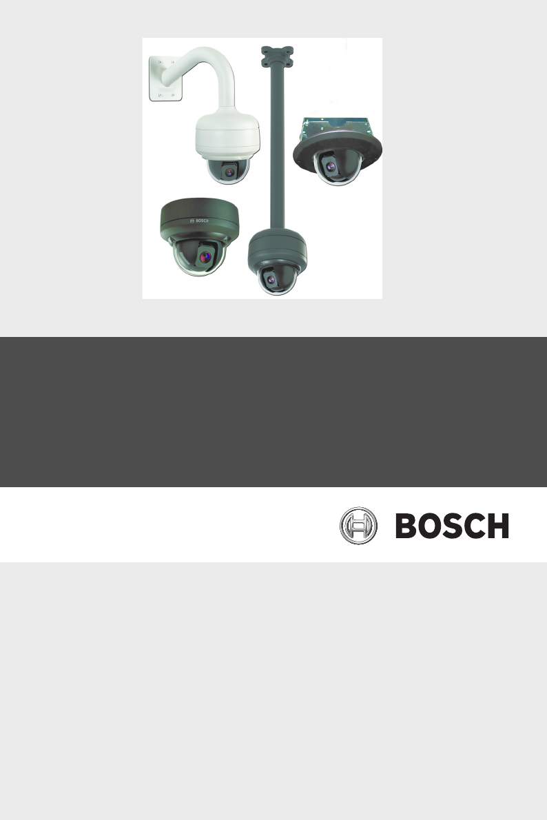
AutoDome Junior HD 3 Description | en 21 Description The AutoDome Junior is part of a larger building block for any surveillance/security system. By using multiple keyboard controllers and multiple dome cameras, no place is too large for monitoring. Extensible and flexible architecture facilities remote control functions for a variety of external switching devices such as multiplexers and DVRs (see the figure below).
en | Description AutoDome Junior HD This installation should be made by qualified service personnel and conform to the National Electrical Code and applicable local codes. NOTICE! A grounded conduit is required in order to meet the EMC Regulation Requirements. F.01U.275.803 | 6.0 | 2012.11 Installation Manual Bosch Security Systems, Inc.
AutoDome Junior HD Installing a Surface Mount | en 4 Installing a Surface Mount 4.1 Description 23 This chapter details how to mount the AutoDome Junior to a hard surface. The AutoDome Junior is also suitable for wall (Section 5 Installing a Wall Mount, page 34), recess (Section 6 Installing a Recessed Mount, page 46), and pipe mounting (Section 7 Installing a Pipe Mount, page 66). For specific directions on mounting the unit, see the manual that came with your mount.
en | Installing a Surface Mount 4.1.1 AutoDome Junior HD Additional Tools Required – Appropriate straight slot screwdrivers – No. 2 Phillips screwdriver – Appropriate tool for cutting a hole in drywall or ceiling tile (if applicable) – 4 in. x 4 in. Junction box with 90 mm (3.54 in.
AutoDome Junior HD 2. Installing a Surface Mount | en 25 Install a 4 in. gang box or square metal junction box (not supplied). Ensure junction box and mounting screws are capable of supporting a maximum load of 11.33 kg (25 pounds). 90 mm (3.54 in.) Figure 4.2 Install User-supplied Junction Box 3. Secure the mounting plate to the junction box with the user supplied hardware (see Figure 4.3). mm .16 121 . 7 in 4.7 40 1.5 .0 m 7i m n. Figure 4.3 Install the Mounting Plate 1 2 3 4 4.
en | Installing a Surface Mount 4.1.3 AutoDome Junior HD Preparing the Surface Mount for an Outdoor Installation The following instructions detail the preparation necessary to prepare the surface and the steps to install the Surface Mount Adapter for an outdoor application. 1. Determine a secure location for the surface mount adapter and the dome. The illustration below shows the placement of the surface mount adapter (item 1, below) and the dome (item 2). ø 175.0 (6.89) 207.2 (8.16) R64.2 (2.
AutoDome Junior HD 2. Installing a Surface Mount | en 27 Use the VEZ-A2-JC or VEZ-A2-JW Surface Mount Adapter as a template to mark the location of the four (4) M4 or #10 pan head screws (Item 1, below). Figure 4.5 Location of M4 or #10 pan head screws 3. Drill the four (4) holes in the installation location. Use a minimum screw length of 10 mm (.39 in.). 4. Prepare the surface so that it can support a maximum load of 11.33 kg (25 lbs). 5. Thread the four (4) 3.97 mm I.D. by Ø1.
en | Installing a Surface Mount b. AutoDome Junior HD Thread the flat side of the gasket (item 1, below) onto the recessed side of the retaining ring (item 2). The illustration below shows a cross-section of the gasket on the retaining ring. CAUTION! You must ensure that the gasket is attached to the retaining ring as shown above to ensure an environmentally tight seal. 7. Attach the retaining ring with gasket (item 2, below) to the Surface Mount Adapter.
AutoDome Junior HD Installing a Surface Mount | en 1 M3 – .5 x 6 Phillips flat head machine screws 2 (supplied with AutoDome Junior Outdoor Camera) Retaining ring with gasket 3 (supplied with AutoDome Junior Outdoor Camera) O-ring, 3.97 mm I.D. by Ø1.78 mm 4 (supplied with AutoDome Junior Outdoor Camera) User-supplied M4 or #10 pan head screws 8. 29 Determine the side of the Surface Mount Adapter in which the external wires are to be routed and remove the plug from the knockout. 9.
en | Installing a Surface Mount AutoDome Junior HD 11. Route the external wires through the conduit and into the Surface Mount Adapter. CAUTION! All wires for installation applications must be routed through a grounded conduit. 12. Secure the mounting plate to the Surface Mount Adapter with the three (3) M4 – .7 x 8 Phillips pan head machine screws. 40 1.5 .0 m 7i m n. Figure 4.8 1 2 Install the Mounting Plate Junction Box Holes Cable Hole (40 mm maximum); Crescent Shape 13. Skip to Section 4.1.
AutoDome Junior HD 5. Installing a Surface Mount | en 31 Unlock the single safety locking screw on the base of the unit using the user-supplied Allen wrench. Figure 4.9 Unlock Safety Locking Screw 6. Plug the matching connectors from the camera into the mating connectors from the ceiling. Figure 4.10 1 2 3 7. Connect Cables Locking Screw Vertical Tab Mounting Plate Align wires on side of mounting plate with crescent shaped cut-out. Bosch Security Systems, Inc. Installation Manual F.01U.275.
en | Installing a Surface Mount 8. AutoDome Junior HD Attach the camera to the mounting plate by inserting the vertical tab on the plate (item 1, below) into the recessed slot on the top of the camera dome (Item 3) to the right of the safety locking screw (item 2). Note: Do not loosen the three brass buttons (item 4). These brass buttons engage the slotted tabs (item 5) on the mounting plate. Figure 4.
AutoDome Junior HD 9. Installing a Surface Mount | en 33 Rotate the camera approximately 15 degrees in a clockwise direction to lock firmly into place, as shown in the next illustration. 5 Figure 4.12 1 Attach Dome to Mounting Plate Vertical tab 10. Secure the safety locking screw with the user supplied locking torx wrench (T-10). Bosch Security Systems, Inc. Installation Manual F.01U.275.803 | 6.0 | 2012.
en | Installing a Wall Mount AutoDome Junior HD 5 Installing a Wall Mount 5.1 Description This chapter details how to mount the AutoDome Junior to a wall. The AutoDome Junior is also suitable for surface (Section 4 Installing a Surface Mount, page 23), recess (Section 6 Installing a Recessed Mount, page 46), and pipe mounting (Section 7 Installing a Pipe Mount, page 66). For specific directions on mounting the unit, see the manual that came with your mount.
AutoDome Junior HD 5.1.2 Installing a Wall Mount | en 35 Preparing the Wall Mount for an Indoor or Installation Use the following instructions to mount to an indoor wall. 1. Determine a secure location for the wall mount (supplied separately). NOTICE! The fasteners and mounting surface must be capable of supporting a maximum load of 11.33 kg (25 pounds). 366.0 (14.1) 333.0 (13.11) 220.4 (8.68) 291.0 (11.46) Figure 5.1 Wall Mount Dimensions 2.
en | Installing a Wall Mount 3. AutoDome Junior HD Attach a grounded metal conduit to the junction box clamp. Figure 5.2 Metal Conduit 4. Feed the wires through the conduit. 5. Feed all wires from the metal junction box through the 6. Attach the mounting cap to the arm. 7. Fit the arm to a metal single-gang junction box. arm. Figure 5.3 F.01U.275.803 | 6.0 | 2012.11 Fit to Gang Junction Box Installation Manual Bosch Security Systems, Inc.
AutoDome Junior HD 8. Installing a Wall Mount | en 37 Secure with the appropriate user-provided SEMS screws that have an integral lock washer to dig through the paint and ensure an electrical ground connection to the arm housing or ground lug. NOTICE! The metal junction box and mounting surface must be capable of supporting a maximum load of 11.33 kg (25 pounds). 9. Skip to Section 5.1.4 Installing the Camera to the Mounting Plate, page 41, to continue the installation. Bosch Security Systems, Inc.
en | Installing a Wall Mount 5.1.3 AutoDome Junior HD Preparing the Wall Mount for an Outdoor Installation The following instructions detail the surface preparations and the steps to install the Wall Mount for an outdoor application. 1. Determine a secure location for the wall mount (supplied separately). NOTICE! The fasteners and mounting surface must be capable of supporting a maximum load of 11.33 kg (25 pounds). 366.0 (14.1) 333.0 (13.11) 220.4 (8.68) 291.0 (11.46) Figure 5.4 2.
AutoDome Junior HD Installing a Wall Mount | en 39 a. Locate the flat side of the gasket and the recessed b. Thread the flat side of the gasket (item 1, below) onto side of the retaining ring. the recessed side of the retaining ring (item 2). The illustration below shows a cross-section of the gasket on the retaining ring. CAUTION! You must ensure that the gasket is attached to the retaining ring as shown above to ensure an environmentally tight seal. Bosch Security Systems, Inc.
en | Installing a Wall Mount 6. AutoDome Junior HD Attach the mounting cap to the arm. Using the AutoDome Junior Outdoor Installation Kit, apply the following O-ring and the retaining ring to the locations specified below: Figure 5.5 1 2 3 a. O-ring and retaining ring placement for outdoor installation O-ring; 21.82 mm I.D. by Ø3.00 mm Retaining ring with gasket M3 – .5 x 6 Phillips flat head machine screws Thread the 21.82 mm I.D. by Ø3.00 mm O-ring (item 1, above) onto the lower arm threads.
AutoDome Junior HD 8. Installing a Wall Mount | en 41 Place the Wall Mount flat gasket (item 1, below), between the surface and Wall Mount; then secure the mount using four (4) appropriate user-provided fasteners such as Moly or Toggle bolts. The flat gasket is supplied with the AutoDome Junior Outdoor Camera. Figure 5.6 Secure arm to wall with flat gasket 9. Skip to Section 5.1.4 Installing the Camera to the Mounting Plate, page 41, to continue the installation. 5.1.
en | Installing a Wall Mount AutoDome Junior HD 40 1.5 .0 m 7i m n. Figure 5.7 1 2 Attach Mounting Plate to Dome Cap Cable Hole (40 mm maximum; crescent shape) Mounting Screws for Dome Cap 2. Route wires on side of mounting plate with crescent 3. Attach grounding wire from unit to the mounting cap. 4. Attach user supplied ground to junction box. shaped cut-out (Ref. #2 Figure 5.7). 5.
AutoDome Junior HD 6. Installing a Wall Mount | en 43 Unlock the single safety locking screw on the base of the unit using the user-supplied Allen wrench. Figure 5.8 Unlock Safety Locking Screw 7. Plug the matching connectors from the camera into the mating connectors from the ceiling. Figure 5.9 Connect Cables 8. Align wires on side of mounting plate with crescent shaped cut-out. Bosch Security Systems, Inc. Installation Manual F.01U.275.803 | 6.0 | 2012.
en | Installing a Wall Mount 9. AutoDome Junior HD Attach the camera to the mounting plate by inserting the vertical tab on the plate (item 1, below) into the recessed slot on the top of the camera dome (Item 3) to the right of the safety locking screw (item 2). Note: Do not loosen the three brass buttons (item 4). These brass buttons engage the slotted tabs (item 5) on the mounting plate. Figure 5.
AutoDome Junior HD Installing a Wall Mount | en 45 10. Rotate the camera approximately 15 degrees in a clockwise direction to lock firmly into place, as shown in the next illustration. Note: Do not loosen brass mounting buttons. Figure 5.11 Attach Dome to Mounting Plate 11. Secure the safety locking screw with the user supplied locking torx wrench (T-10). 12. Pull excess wire back into the mount tube. 13. Confirm that the housing is electrically grounded. Bosch Security Systems, Inc.
en | Installing a Recessed Mount AutoDome Junior HD 6 Installing a Recessed Mount 6.1 Description This chapter details how to install an AutoDome Junior into an indoor ceiling space or into an outdoor soffit. You must use the VJR-A3-IC54 AutoDome Junior IP54-rated In-ceiling mount kit (sold separately) if your indoor application must be plenum rated or rated to the IP54 standard. All outdoor recessed applications must use the VJR-A3-IC54 kit.
AutoDome Junior HD 6.2 Installing a Recessed Mount | en 47 Indoor Recessed Installation NOTICE! This section provides instructions for installing an AutoDome Junior into an indoor ceiling space that does not require an IP54 or a plenum rating. Refer to Section 6.3 Outdoor and IP54 Recessed Installation, page 55, for an indoor installation that requires these certifications.
en | Installing a Recessed Mount 6.2.2 AutoDome Junior HD Preparing the Ceiling for Installation To mount to a recess mount, do the following: 1. Determine a secure location for the recessed mount (supplied separately). 104.9 (4.13) 71.6 (2.82) mm (in.) Figure 6.1 2. 229.0 (9.02) Recess Mount Dimensions Drill or cut a 200 mm hole with a tolerance of 2.2 mm (7.9 in. ± 1/8). 3.
AutoDome Junior HD 4. Installing a Recessed Mount | en 49 Align holes of mounting plate (supplied with dome) with mounting bracket and attach with screws. Ensure that both the crescent shape of the mounting plate and the crescent shape of the mounting bracket are aligned. Figure 6.2 Attach Mounting Plate to Mounting Bracket 1 2 3 4 5 5.
en | Installing a Recessed Mount 6. AutoDome Junior HD Insert mount through the hole in the ceiling. Slide clamps out and down so that the ceiling/drywall is captured in between the clamps and the bracket flange. The ceiling/ drywall must have a maximum thickness of 41.7 mm (1.64 in.) and an minimum thickness of 12.7 mm (0.50 in.). Figure 6.3 7. Attach Recess Mount to Ceiling Tighten both clamps using the clamp drive screws (installed on the assembly) and a #2 Phillips screwdriver. Figure 6.
AutoDome Junior HD Installing a Recessed Mount | en 51 NOTICE! If you need to install the VJR-A3-SP Support Bracket, refer to the guide included with the bracket. Once the bracket is installed, continue with the next section. 6.2.3 Installing the Camera to the Mounting Plate To install the base to a surface or suspended ceiling using the supplied mounting plate, do the following: 1. Loosen the single safety locking screw on the base of the unit using the user-supplied T-10 Torx wrench. Figure 6.
en | Installing a Recessed Mount 6. AutoDome Junior HD Connect the mating connectors (supplied in the accessory kit) with the flying leads to the user supplied wiring (see the Section 8 Preparing the Wiring, page 77 for wiring information). 7. Plug the matching connectors from the camera into the mating connectors from the ceiling. Figure 6.6 1 2 3 4 8.
AutoDome Junior HD Installing a Recessed Mount | en 53 Figure 6.7 Tab/Slot Alignment Detail 1 2 3 4 5 9. Vertical Tab (on mounting plate) Locking Screw Recessed Slot (on dome housing) Brass Button (total of three on housing) Slotted Tab (total of three on mounting plate) Rotate the camera approximately 15 degrees in the clockwise direction. Then, lock firmly into place, as shown in the next illustration. Figure 6.8 Attach Dome to Mounting Plate 1 2 3 Bosch Security Systems, Inc.
en | Installing a Recessed Mount 10. AutoDome Junior HD Ensure unit is centered. NOTICE! The recessed mounting bracket is provided with an additional safety tether point. To prevent injury, attach a safety wire from a secure anchor point above the ceiling to this tether point. 11. Align trim ring so the four alignment posts (item 1, below) align with the recesses in the camera housing (item 2) and so the two safety screws align with the off center holes (item 3) on the locking clamps.
AutoDome Junior HD 6.3 Installing a Recessed Mount | en 55 Outdoor and IP54 Recessed Installation This section details the steps to install an AutoDome Junior into an indoor ceiling space that requires IP54 or a plenum rating or into an outdoor soffit. This installation requires the use of the VJR-A3-IC54 AutoDome Junior IP54-rated In-ceiling mount kit (sold separately). CAUTION! The combined weight of the camera and ceiling mount is approximately 3.76 kg (7 lb).
en | Installing a Recessed Mount 6.3.1 AutoDome Junior HD Installation Requirements – Appropriate straight slot screwdrivers – No. 2 Phillips screwdriver – Appropriate tool for cutting a hole in drywall, ceiling tile, or – T-10 Torx wrench – Retaining ring with gasket other materials used in outdoor soffits (if applicable) (supplied with AutoDome Junior camera kit) – Three (3) M3 – .
AutoDome Junior HD 2. Installing a Recessed Mount | en 57 Drill or cut a 200 mm hole with a tolerance of 2.2 mm (7.9 in. ± 1/8). 3. Optional: if installing the AutoDome Junior to a suspended ceiling tile or any other surface where additional support is required, the VJR-A3-SP mounting kit is recommended (supplied separately). 4. Ensure that the gasket is attached to the retaining ring. If the gasket and the retaining ring are separate: a. Locate the flat side of the gasket and the recessed b.
en | Installing a Recessed Mount 5. AutoDome Junior HD Attach the retaining ring with gasket (item 2, below, supplied with the AutoDome Junior camera) to the VJR-A3JW. Ensure that the side of the retaining ring with the counter-sunk screw holes is facing you. Figure 6.12 O-ring and retaining ring placement for outdoor installation 1 M3 – .5 x 6 Phillips flat head machine screws 2 (supplied with AutoDome Junior Camera) Retaining ring with gasket (supplied with AutoDome Junior Camera) 6.
AutoDome Junior HD Installing a Recessed Mount | en 59 10. Attach the VJR-A3-JW to the mounting bracket using the four (4) M4 x 16 Phillips Pan Head Machine Screws (item 2, below). Figure 6.13 Attach VJR-A3-JW to Mounting Bracket 11. Align the holes of mounting plate with the VJR-A3-JW junction box and attach with the three (3) M4–.7 x 8 Phillips Pan Head Machine Screws. Note the alignment of the mounting plate relative to the VJR-A3-JW junction box. Figure 6.14 Bosch Security Systems, Inc.
en | Installing a Recessed Mount AutoDome Junior HD NOTICE! If you need to install the VJR-A3-SP Support Bracket, refer to the guide included with the bracket. Once the bracket is installed, continue with the next section. 12. Loosen the two clamp drive screws (item 1, below) so that the clamping plates (item 2) move freely. Figure 6.15 Clamp Drive Screws and Plates 13. Insert the bracket through the hole in the ceiling.
AutoDome Junior HD Installing a Recessed Mount | en 61 14. Tighten both clamps using the clamp drive screws (installed on the assembly) and a #2 Phillips screwdriver. Figure 6.17 Tighten Mounting Clamps NOTICE! Over-torquing the ceiling clamps can damage the clamp or ceiling. Only tighten the clamp until it contacts the ceiling and you start to feel some resistance. If using a power screwdriver, set the torque level to the lowest setting. 6.3.
en | Installing a Recessed Mount AutoDome Junior HD CAUTION! All wires for installation applications must be routed through a grounded conduit. 2. Remove the screw from the Earth ground ( )on the inside of the VJR-A3-JW. 3. Attach a user-supplied ground wire to the Earth ground ( ) screw hole on the VJR-A3-JW and secure with the screw. 4. Attach the green grounding wire from the unit to the grounded ( ) screw hole on the VJR-A3-JW using the attached captive screw washer. 5. 6.
AutoDome Junior HD 8. Installing a Recessed Mount | en 63 Attach the camera to the mounting plate by inserting the vertical tab on the plate (item 1, below) into the recessed slot on the top of the camera dome (Item 3) to the right of the safety locking screw (item 2). Note: Do not loosen the three brass buttons. These brass buttons engage the slotted tabs on the mounting plate. Figure 6.19 1 2 3 Bosch Security Systems, Inc.
en | Installing a Recessed Mount 9. AutoDome Junior HD Rotate the camera approximately 15 degrees in the clockwise direction. Then, lock firmly into place, as shown in the next illustration. Figure 6.20 10. Attach Dome to Mounting Plate Ensure unit is centered. NOTICE! The recessed mounting bracket is provided with an additional safety tether point (item 1, Figure 6.20). To prevent injury, attach a safety wire from a secure anchor point above the ceiling to this tether point. F.01U.275.803 | 6.
AutoDome Junior HD Installing a Recessed Mount | en 65 11. Align trim ring so the four alignment posts (item 1, below) align with the recesses in the camera housing (item 2) and so the two safety screws align with the off center holes (item 3) on the locking clamps. Note: The two (2) sets of raised stand-off tabs (item 4) on each side of the trim ring align with the locking clamps. Figure 6.
en | Installing a Pipe Mount AutoDome Junior HD 7 Installing a Pipe Mount 7.1 Description This chapter details how to mount the AutoDome Junior to a pipe. The AutoDome Junior is also suitable for surface (Section 4 Installing a Surface Mount, page 23), wall (Section 5 Installing a Wall Mount, page 34), and recess mounting (Section 6 Installing a Recessed Mount, page 46). For specific directions on mounting the unit, see the manual that came with your mount.
AutoDome Junior HD 7.1.1 Installing a Pipe Mount | en 67 Tools/Supplies Required – Appropriate straight slot screwdrivers – No. 2 Phillips screwdriver – Appropriate tool for cutting a hole in drywall or ceiling tile (if applicable) – T-10 Torx wrench – Ground Lug (outdoor use only) – AutoDome Junior Camera, required for an outdoor installation 7.1.
en | Installing a Pipe Mount 2. AutoDome Junior HD Use the four (4) holes in the flange as a template to mark the position where the holes should be drilled to secure the mount. Figure 7.2 3. Mark Flange Holes Drill the four (4) holes in the installation location, screws not supplied, use a minimum screw length of 10 mm (.39 in.). CAUTION! All wires for installation applications must be routed through a grounded conduit. 4. Drill a fifth hole (maximum of 20 mm [.79 in.
AutoDome Junior HD Installing a Pipe Mount | en 69 Figure 7.3 Location of O-rings for an outdoor installation 1 2 a. O-ring; 21.82 mm I.D. by Ø3.00 mm O-ring; 29.74 mm I.D. by Ø3.00 mm Thread a 21.82 mm I.D. by Ø3.00 mm O-ring (item 1, above) between the flange threads and the upper coupler threads. b. Thread a 29.74 mm I.D. by Ø3.00 mm O-ring (item 2, above) between any interface between a pipe and a coupler. Bosch Security Systems, Inc. Installation Manual F.01U.275.803 | 6.0 | 2012.
en | Installing a Pipe Mount 6. AutoDome Junior HD Outdoor Installation: Ensure that the gasket is attached to the retaining ring. If the gasket and the retaining ring are separate: a. Locate the flat side of the gasket and the recessed side of the retaining ring. b. Thread the flat side of the gasket (item 1, below) onto the recessed side of the retaining ring (item 2). The illustration below shows a cross-section of the gasket on the retaining ring.
AutoDome Junior HD Installing a Pipe Mount | en 71 Figure 7.4 O-ring and retaining ring placement for outdoor installation 1 2 3 4 O-ring; 21.82 mm I.D. by Ø3.00 mm Dome Cap Retaining ring with gasket M3 – .5 x 6 Phillips flat head machine screws a. Thread the 21.82 mm I.D. by Ø3.00 mm O-ring (item 1, b. Secure the retaining ring gasket (item 2, above) to the above) onto the lower pipe threads. dome cap with the three (3) M3 – .5 x 6 Phillips flat head machine screws.
en | Installing a Pipe Mount AutoDome Junior HD NOTICE! The fasteners and mounting surface must be capable of supporting a maximum load of 11.33 kg (25 pounds). 9. Pull the wires from the pipe, starting at the flange end. Figure 7.5 Attach Pendant Pipe Mount to Ceiling CAUTION! Select a rigid mounting location to prevent excessive vibration to the AutoDome Junior Camera. F.01U.275.803 | 6.0 | 2012.11 Installation Manual Bosch Security Systems, Inc.
AutoDome Junior HD Installing a Pipe Mount | en 73 10. Attach user supplied ground lug. 11. Align holes of mounting plate (supplied with dome) with dome mounting cap and attach with the three (3) screws supplied. Figure 7.6 Attach Mounting Plate to Dome Cap 1 2 3 4 Bosch Security Systems, Inc. Crescent Shape Ground Lug Dome Cap Mounting Plate Installation Manual F.01U.275.803 | 6.0 | 2012.
en | Installing a Pipe Mount 7.1.3 AutoDome Junior HD Installing the Camera to the Mounting Plate To install the camera to a ceiling mount using the supplied mounting plate, do the following: 1. Route wires on side of mounting plate with crescent shaped cut-out. 2. Attach grounding wire from unit to mounting cap. 3. Attach user supplied ground to junction box. 4.
AutoDome Junior HD Installing a Pipe Mount | en 75 Note: Do not loosen brass mounting buttons. Figure 7.8 Tab/Slot Alignment Detail 1 2 3 4 5 Bosch Security Systems, Inc. Vertical Tab (on mounting plate) Locking Screw Recessed Slot (on dome housing) Brass Button (total of three on housing) Slotted Tab (total of three on mounting plate) Installation Manual F.01U.275.803 | 6.0 | 2012.
en | Installing a Pipe Mount 9. AutoDome Junior HD Rotate the camera approximately 15 degrees in the clockwise direction and lock firmly into place, as shown in the next illustration. Figure 7.9 Attach Dome to Mounting Plate 10. Secure the safety locking screw with the user supplied locking torx wrench (T-10). 11. Pull excess wire back into the mount tube. 12. Confirm that the housing is electrically grounded. F.01U.275.803 | 6.0 | 2012.11 Installation Manual Bosch Security Systems, Inc.
AutoDome Junior HD 8 Preparing the Wiring | en 77 Preparing the Wiring All AutoDome Junior HD units provide three standard cables: an Ethernet cable, a 24 VAC power input cable for the camera, and an alarm input/output cable. An Outdoor AutoDome Junior HD unit provides an additional 24 VAC power input cable for the heater. The Ethernet connection carries control and video information and can deliver power to the camera via the Power-overEthernet Plus (PoE+) standard.
en | Preparing the Wiring 8.2 AutoDome Junior HD Connecting the Power The AutoDome Junior HD is available as an indoor or an outdoor model. Power to the camera in all models is supplied either via a single 24 VAC isolated power connector (red and black wires) or via a Power over Ethernet + (PoE+, IEEE 802.3at, class 4) connection using the existing CAT 5E Ethernet cable. Power to the heater is supplied via a single 24 VAC isolated power connector (white/red and white/black wires).
AutoDome Junior HD 8.2.1 Preparing the Wiring | en 79 Power Connections to Indoor/Outdoor Cameras WARNING! The indoor or outdoor AutoDome Junior HD camera can accept power from the 24 VAC power input or from the Ethernet input. Ensure that the camera receives power from only one source. Refer to Section 8.3 Ethernet Connection, page 81, for more information about connecting Power over Ethernet. Figure 8.1 Ref.
en | Preparing the Wiring 8.2.2 AutoDome Junior HD Power Connections to Heater (all outdoor models) The heater in an outdoor AutoDome Junior HD unit accepts power only from a single 24 VAC isolated power connector (white/red and white/black wires). The heater does not accept power via Power over Ethernet + (PoE+, IEEE 802.3at, class 4). Figure 8.2 Ref.
AutoDome Junior HD 8.3 Preparing the Wiring | en 81 Ethernet Connection The AutoDome Junior HD connects to a 10 Base-T/100 Base-TX network either directly or via a switch. Both video and control are transmitted over a standard TCP/IP network using the builtin Web server. In addition, power is supplied to an AutoDome Junior HD camera via the Ethernet cable compliant with the Power-over-Ethernet + (IEEE 802.3at, class 4) standard.
en | Audio, Alarms and Relay Connections AutoDome Junior HD 9 Audio, Alarms and Relay Connections 9.1 Alarm Input All AutoDome Junior models provide connections for two alarm inputs, one alarm output, and one audio input. Each alarm input can be activated by dry contact devices such as pressure pads, passive infrared detectors, door contacts, and similar devices. AUDIO IN AUDIO GND GROUND ALARM IN 2 ALARM IN 1 ALARM OUT BLU YEL ORG GRN BRN WHT Figure 9.
AutoDome Junior HD 9.2 Audio, Alarms and Relay Connections | en 83 Connecting Alarms (inputs 1 through 2) You can configure alarms 1 through 2 as Normally Open (N.O.) or Normally Closed (N.C.) alarms. 9.2.1 Connecting a Normally Open Alarm 1. Connect the alarm to the appropriate input (1 through 2) and ground at the AutoDome Junior. Figure 9.2 N.O. - Normally Open Ref. # User Contact Dome 1 Normally Alarm In 1 or Alarm In 2 2 2. Open Common (Ref. #3) Ground (Ref.
en | Audio, Alarms and Relay Connections 9.2.2 AutoDome Junior HD Connecting a Normally Closed Alarm 1. Connect the alarm to the appropriate input (1 through 2) and ground at the AutoDome Junior. Figure 9.3 N.C. Normally Closed Connections Ref. # User Contact Dome 1 Normally Alarm In 1 or Alarm In 2 2 2. Closed Common (Ref. #3) Ground (Ref. #4) Color Brown IN 1 or Orange IN 2 Green From the AutoDome Junior HD Settings page select Interface>Alarm Inputs.
AutoDome Junior HD 9.3 Audio, Alarms and Relay Connections | en 85 Alarm Outputs The AutoDome Junior incorporates one (1) alarm output: an open collector output. NPN C B E Figure 9.4 Ref. # 1 2 3 4 5 6 9.3.1 -- -- -- -- -- -- -- -- -- -- -- -- -- -- -- -- -- -- -- -- -- -- -- -- -- -- -- -- -- -- -- -- -- -- -- -- -- -- -- -- -- -- -- -- -- -- -- -- -- -- -- -- -- -- -- -- -- -- -- -- -- -- -- -- N.O.
en | Audio, Alarms and Relay Connections AutoDome Junior HD Max. Input Voltage 5.5 Vpp Impedance 9KΩ Sample Rate G.711: 8 bits @ 8 KHzL16: 16 bits @ 16 kHz PCM Shield Bare copper braid: 95% coverage Internal gain level adjustment is available Wire Specifications Wire Type Coax3 (recommended) Distance 10 m (33 ft) Gage 22 AWG Shield Bare copper braid: 95% coverage Center conductor Stranded bare copper F.01U.275.803 | 6.0 | 2012.11 Installation Manual Bosch Security Systems, Inc.
AutoDome Junior HD 10 Getting Started | en 87 Getting Started Once the installation is complete, the AutoDome Junior HD can be programmed. A typical system may include a keyboard, matrix switcher, monitor, appropriate wiring connections, and a PC with Internet Explorer. Please refer to the individual product manuals for complete installation and setup instructions for each of the system components. 10.
11 en | Using the IP Interface AutoDome Junior HD Using the IP Interface The AutoDome Junior HD transmits PTZ control commands and images over a TCP/IP network. It also allows users to configure the camera display settings, camera operating settings, and to configure the network parameters. The HD unit incorporates a network video server in the IP module. The primary function of the server is to encode video and control data for transmission over a TCP/IP network. With its H.
AutoDome Junior HD 11.1 Using the IP Interface | en 89 Overview of Features The AutoDome Junior HD module includes the following functionality: Function Description Video Encoding The camera uses the H.264 compression standards and ensures that the data rate remains low even with high image quality and can also be adapted to local conditions within wide limits. Streaming Encodes multiple data streams simultaneously according to individually customized profiles.
en | Using the IP Interface 11.2 AutoDome Junior HD System Requirements The AutoDome Junior HD requires specific software and hardware to allow a user to view live images and to configure camera settings over a TCP/IP network. These requirements are: – A computer with the Microsoft Windows XP, Vista, or Windows 7 operating system, network access, and the Microsoft Internet Explorer Web browser version 9.
AutoDome Junior HD – Using the IP Interface | en 91 Software: – Microsoft Internet Explorer, version 9.0 or higher – Bosch Video Client (BVC) – DirectX 9.0c – MPEG-ActiveX 5.20.0045 or newer – Oracle Java Virtual Machine 1.6.0_26 NOTICE! Ensure the graphics card is set to 16-bit or 32-bit color. If you need further assistance, contact your PC system administrator. 11.3 Connecting the AutoDome Junior HD to the PC 1.
en | Using the IP Interface 1 2 3 4 AutoDome Junior HD AutoDome Junior HD IP Connection Network Switch Computer NOTICE! You can also use the Bosch Configuration Manager utility to configure the network settings for an AutoDome Junior IP or HD camera. Go to www.boschsecurity.com to download the Configuration Manager software and Operating Manual. 11.4 Configuring the AutoDome Junior HD Camera To operate the camera in your network you must assign it a valid network IP address.
AutoDome Junior HD Using the IP Interface | en 93 The AutoDome Junior HD defaults are as follows: – IP Address: 192.168.0.1 – Subnet Mask: 255.255.255.0 – Gateway IP Address: 0.0.0.0 The following sections provide instructions about installing the software necessary to view images over an IP connection, configuring the IP network settings and accessing the AutoDome Junior IP images from a Web browser. 11.4.1 Changing the Network Settings The AutoDome Junior HD has a default IP address of 192.168.
en | Using the IP Interface AutoDome Junior HD 3. Check the Always Trust box, then click YES. 4. Click the Settings link, located at the top of the LivePage. 5. Click the Service Settings link, located in the left pane of 6. Click the Network link to open the Network Settings page. 7. Configure the settings on this page based on the the Settings window. Figure 11.2 Network Settings Page addresses provided by your local network administrator.
AutoDome Junior HD Using the IP Interface | en 8. Click the Set button to save the settings. 9. Launch another instance of Microsoft Internet Explorer. 95 10. Type the original IP address followed by /reset (for example, http://192.168.0.1/reset) in the address bar and click Go to restart the AutoDome Junior IP. Once you restart the AutoDome Junior IP, use the new IP Address to access the LivePage. 11.
en | Using the IP Interface AutoDome Junior HD Display Stamping Various overlays or “stamps” in the video image provide important status information. The overlays provide the following information: Decoding error. The frame might show artefacts due to decoding errors. If subsequent frames reference this corrupted frame, they might also show decoding errors as well but won’t be marked with the “decoding error” icon. Alarm flag set on media item Communication error.
AutoDome Junior HD Using the IP Interface | en 97 Maximum Number of Connections If you do not connect, the unit may have reached its maximum number of connections. Depending on the unit and network configuration, each AutoDome Junior IP can have up to 25 Web browser connections or up to 50 connections via the Bosch Video Management System.
en | Using the IP Interface AutoDome Junior HD View Control The View Control tab allows you to control camera functions (pan, tilt, zoom, focus, and iris), navigate through on-screen menus and to view preset shots.
AutoDome Junior HD 3. Using the IP Interface | en 99 To manually pan throughout the image area, move your cursor over any part of the live video. The image area displays a directional arrow ( , then click and hold the right mouse key to pan the camera. Digital I/O The alarm icon is for information purposes and indicates the status of an alarm input: When an alarm is triggered, the icon lights up blue.
en | Using the IP Interface AutoDome Junior HD Events such as the triggering or end of alarms are shown in the Event Log field. You can save these messages automatically in a file (see the AutoDome Junior online help). 1. If you want to delete the entries, click the delete icon in the top right-hand corner of the relevant field. 2. If you want to view a detailed log, click the icon in the top right-hand corner of the relevant field. A new window will open. 11.5.
AutoDome Junior HD Using the IP Interface | en 101 To Enter a Keyboard Control Command: 1. Place the cursor in the Command Number field. 2. Click the desired command number via the on-screen keypad. 3. Click either the Aux On or the Aux Off button to initiate or stop the command. 4. If the command initiates a menu, use the Up/Down arrows on the View Control to navigate the menu. Click the Focus or Iris button to select a menu item.
en | Using the IP Interface 11.5.2 AutoDome Junior HD Using Special Functions The AutoDome offers several special command buttons on the Livepage. Scan 360 Click this button to start a continuous 360° pan. To stop the continuos pan, click a directional control in the View Control tab. Autopan Click this button to pan the AutoDome between user-defined limits. To set the left and right pan limits, refer to Section 12.22 PTZ Settings, page 137, so set the Autopan limits.
AutoDome Junior HD 11.6 Using the IP Interface | en 103 Commissioning the AutoDome Junior Fixed Camera The remote commissioning feature simplifies installation by allowing operators to position and zoom the camera via a remote head-end unit. This section provides instructions for setting the position and the zoom level for an AutoDome Junior HD Fixed camera (VJRF801 Series). Using the Built-in Web Server: 1.
en | Using the IP Interface 11.7 AutoDome Junior HD Saving Snapshots You can save individual images from the video sequence currently shown on the Livepage in JPEG format on your computer's hard drive. The icon for recording single images is only visible if the unit is configured to enable this process. Click the icon. The storage location depends on the configuration of the AutoDome Junior HD. 11.
AutoDome Junior HD 11.9 Using the IP Interface | en 105 Processor Load If the AutoDome Junior IP is accessed via the Web browser, you will see the processor load indicator in the top left of the window next to the manufacturer's logo. You can obtain additional information to help when you troubleshoot or fine-tune the unit. The values indicate the proportions of the individual functions on the encoder load, shown as percentages. Move the cursor over the graphic indicator.
en | Using the IP Interface AutoDome Junior HD Controlling a Playback You will see a time bar below the video image for quick orientation. A green arrow above the bar indicates the position of the image currently being played back within the sequence. The time bar offers various options for navigation. Red bars indicate the points in time where alarms were triggered. Drag the green arrow to navigate to these points quickly. 1.
AutoDome Junior HD Using the IP Interface | en 107 Bookmarks In addition, you can set markers in the sequences, so-called bookmarks, and leap directly to these. These bookmarks are indicated as small yellow arrows above the time interval. Use the bookmarks as follows: Jump to the previous bookmark Set bookmark Jump to the following bookmark NOTICE! Bookmarks are only valid while you are in the PLAYBACK page; they are not saved with the sequences. As soon as you leave the page all bookmarks are deleted.
en | Configuring the AutoDome Junior HD 12 AutoDome Junior HD Configuring the AutoDome Junior HD The SETTINGS page provides access to the configuration menu, which contains all the unit's parameters arranged in groups. You can view the current settings by opening one of the configuration screens. You can change the settings by entering new values or by selecting a predefined value from a list field.
AutoDome Junior HD 2. Configuring the AutoDome Junior HD | en 109 Click one of the entries in the submenu. The Web browser opens the corresponding page. Making Changes Each configuration screen shows the current settings. You can change the settings by entering new values or by selecting a predefined value from a list field. After each change, click Set to save the change. CAUTION! Save each change with the associated Set button. Clicking the Set button saves the settings only in the current field.
en | Configuring the AutoDome Junior HD AutoDome Junior HD The highest authorization level is service. After entering the correct password, you can access all the functions of the AutoDome Junior HD and change all configuration settings. With the user authorization level, you can operate the unit and also control cameras, for example, but you cannot change the configuration. The lowest authorization level is live.
AutoDome Junior HD 12.2 Configuring the AutoDome Junior HD | en 111 Basic Mode: Date/Time Device date/Device time/Device time zone If there are multiple devices operating in your system or network, it is important to synchronize their internal clocks. For example, it is only possible to identify and correctly evaluate simultaneous recordings when all units are operating on the same time. If necessary, you can synchronize the unit with your computer's system settings.
en | Configuring the AutoDome Junior HD AutoDome Junior HD CAUTION! If you change the IP address, subnet mask or gateway address, the AutoDome Junior HD is only available under the new addresses after the reboot. DHCP If a DHCP server is employed in the network for the dynamic assignment of IP addresses, you can activate acceptance of IP addresses automatically assigned to the AutoDome Junior HD.
AutoDome Junior HD 12.4 Configuring the AutoDome Junior HD | en 113 Basic Mode: Encoder Default profile You can select a profile for encoding the video signal. You can use this to adapt the video data transmission to the operating environment (for example network structure, bandwidth, data load). Pre-programmed profiles are available, each giving priority to different perspectives. When selecting a profile, details are displayed in the list field.
en | Configuring the AutoDome Junior HD – AutoDome Junior HD Modem Target bit rate: 20 kbps Maximum bit rate: 22 kbps Encoding interval: 15.00 ips – GSM Target bit rate: 7 kbps Maximum bit rate: 8 kbps Encoding interval: 7.50 ips 12.5 Basic Mode: Audio You can set the gain of the audio signals to suit your specific requirements. The current video image is shown in the small window next to the slide controls to help you check the audio source and improve assignments.
AutoDome Junior HD 12.6 Configuring the AutoDome Junior HD | en 115 Basic Mode: Recording You can record the images from the AutoDome Junior HD on various local storage media or on an appropriately configured iSCSI system. Here you can select a storage medium and immediately start the recording. Storage medium 12.7 1. Select the required storage medium from the list. 2. Click the Start button to start the recording immediately.
en | Configuring the AutoDome Junior HD AutoDome Junior HD Enter a unique, unambiguous name for the camera in this field. You can use both lines for this. CAUTION! Do not use any special characters, for example &, in the name. Special characters are not supported by the system's internal recording management and may therefore result in the Player or Archive Player being unable to play back the recording.
AutoDome Junior HD 12.10 Configuring the AutoDome Junior HD | en 117 Password An AutoDome Junior HD is generally protected by a password to prevent unauthorized access to the unit. You can use different authorization levels to limit access. NOTICE! Proper password protection is only guaranteed when all higher authorization levels are also protected with a password. If a live password is assigned, for example, a service and a user password must also be set.
en | Configuring the AutoDome Junior HD AutoDome Junior HD NOTICE! A new password is only saved when you click the Set button. You should therefore click the Set button immediately after entering and confirming a password. 12.11 Date/Time Date format Select your required date format. Device date/Device time If there are multiple devices operating in your system or network, it is important to synchronize their internal clocks.
AutoDome Junior HD 1. Configuring the AutoDome Junior HD | en 119 First check whether the correct time zone is selected. If it is not correct, select the appropriate time zone for the system, and click the Set button. 2. Click the Details button. A new window will open and you will see the empty table. 3. Select the region or the city that is closest to the system's location from the list field below the table. 4.
en | Configuring the AutoDome Junior HD AutoDome Junior HD 12.12 Advanced Mode: Web Interface 12.13 Appearance On this page you can adapt the appearance of the web interface and change the website language to meet your requirements. If necessary, you can replace the manufacturer's logo (top right) and the product name (top left) in the top part of the window with individual graphics. NOTICE! You can use either GIF or JPEG images.
AutoDome Junior HD 12.14 Configuring the AutoDome Junior HD | en 121 Livepage Functions On this page you can adapt theLivepage functions to your requirements. You can choose from a variety of different options for displaying information and controls. 1. Check the box for the items that are to be made available on the Livepage. The selected items are indicated by a check mark. 2. Check whether the required functions are available on the Livepage.
en | Configuring the AutoDome Junior HD AutoDome Junior HD Show VCA metadata When video content analysis (VCA) is activated, additional information is displayed in the live video stream. For example, in Motion+ mode, the sensor areas for motion detection are marked. Show event log The event messages are displayed along with the date and time in a field next to the video image.
AutoDome Junior HD 12.15 Configuring the AutoDome Junior HD | en 123 Logging Save event log Check this option to save event messages in a text file on your local computer. You can then view, edit and print this file with any text editor or the standard Office software. File for event log 1. Enter the path for saving the event log here. 2. If necessary, click Browse to find a suitable directory. Save system log Check this option to save system messages in a text file on your local computer.
en | Configuring the AutoDome Junior HD AutoDome Junior HD Reboot device Performs a reboot of the AutoDome. There is a ten (10) second pause before the dome starts its homing phase. During the homing phase the camera pans left and right and tilts up and down. It also adjusts the lens focus. The entire homing phase lasts approximately 40 seconds. Factory defaults Click Restore all defaults to restore the factory defaults for the camera. A confirmation screen appears.
AutoDome Junior HD – Configuring the AutoDome Junior HD | en 125 HD High high quality / low latency Target bit rate: 5000 kbps Maximum bit rate: 10000 kbps Encoding interval: 30.00 ips – High Resolution 2 Target bit rate: 1500 kbps Maximum bit rate: 3000 kbps Encoding interval: 30.00 ips – Low Bandwidth Target bit rate: 700 kbps Maximum bit rate: 1500 kbps Encoding interval: 30.00 ips – DSL Target bit rate: 400 kbps Maximum bit rate: 500 kbps Encoding interval: 30.
en | Configuring the AutoDome Junior HD AutoDome Junior HD CAUTION! The profiles are rather complex. They include a large number of parameters that interact with one another, so it is generally best to use the default profiles. Change the profiles only once you are fully familiar with all the configuration options. In the default setting, Stream 2 is transmitted for alarm connections and automatic connections. Bear this fact in mind when assigning the profile.
AutoDome Junior HD Configuring the AutoDome Junior HD | en 127 Maximum data rate This maximum data rate is not exceeded under any circumstances. Depending on the video quality settings for the I- and P-frames, this fact can result in individual images being skipped. The value entered here must be at least 10% higher than the value entered in the Target data rate field. If the value entered here is too low, it will automatically be adjusted.
en | Configuring the AutoDome Junior HD AutoDome Junior HD I-frame Distance This parameter allows you to set the intervals in which the Iframes will be coded. 0 means auto mode, whereby the video server inserts I-frames as necessary. An entry of 1 indicates that I-frames are continuously generated. An entry of 2 indicates that only every second image is an I-frame, and 3 only every third image etc.; the frames in between are coded as P-frames.
AutoDome Junior HD Configuring the AutoDome Junior HD | en 129 HD stream options: – H.264 MP 720p25/30 Fixed – H.264 MP 720p30/60 Fixed – H.264 MP 1080p Fixed SD stream options (use these options if a second H.264 stream is allowed): – H.264 BP+ bit-rate-limited Select this setting when using hardware decoders or the Divar XF digital video recorder. The bit rate is limited to 1.2 Mbps. CABAC: off CAVLC: on GOP structure: IP I-frame distance: 15 Deblocking filter: on – H.
en | Configuring the AutoDome Junior HD AutoDome Junior HD Property Select one of the H.264 standards for each stream. NOTICE! If you select H.264 MP 720p30/60 Fixed or H.264 MP 1080p Fixed as the first stream, you can select only Copy of Stream 1 as an option for stream 2. Default profile Select one of the following profiles for each stream: – HD high quality / low latency – High resolution 2 – Low bandwidth – DSL – ISDN (2B) – ISDN (1B) – Modem – GSM Refer to Section 12.
AutoDome Junior HD 12.19 Configuring the AutoDome Junior HD | en 131 Privacy Masks Privacy Masking is used to block out a specific area of a scene from being viewed. Masks can be configured as a gray area with four corners. You may define a total of 24 privacy masks. NOTICE! – The AutoDome disables the Privacy Mask feature if the orientation of the camera is set to Inverted. Refer to Section 12.16 Installer Menu, page 123, for orientation settings.
en | Configuring the AutoDome Junior HD 7. AutoDome Junior HD Click Set to save the privacy mask size and position. An image window displays the privacy mask. 8. To hide an individual mask, select the mask number and 9. To hide all masks from an image view, click the Hide Masks clear the Enable check box. check box. Note: If you choose to hide all masks, you must enable each enable each individual mask to show the mask in the scene. 12.
AutoDome Junior HD Configuring the AutoDome Junior HD | en 133 Gain Control Adjusts the automatic gain control (AGC). Automatically sets the gain to the lowest possible value needed to maintain a good picture. – AGC (default): electronically brightens dark scenes, which may cause graininess in low light scenes. – Fixed: no enhancement. This setting disables the Max. Gain Level option.
en | Configuring the AutoDome Junior HD AutoDome Junior HD Auto SensUp Maximum Sets the Auto SensUp minimum value for the AutoDome. The Auto SensUp Min. value is the factor by which the sensitivity of the camera is increased. The default setting is 15x. Backlight Compensation Optimizes the video level for the selected area of the image. Parts outside this area may be underexposed or overexposed. Select On to optimize the video level for the central area of the image. The default setting is Off.
AutoDome Junior HD 12.21 Configuring the AutoDome Junior HD | en 135 Lens Settings Auto Focus Continuously adjusts the lens automatically to the correct focus for the sharpest picture. – One Push (default): activates the Auto Focus feature after the camera stops moving. Once focused, Auto Focus is inactive until the camera is moved again. – Auto Focus: Auto Focus is always active. – Manual: Auto Focus is inactive. Focus Polarity – Normal (default): focus controls operate normally.
en | Configuring the AutoDome Junior HD AutoDome Junior HD Iris Polarity Capability to reverse the operation of the iris button on the controller. – Normal (default): iris controls operate normally. – Reverse: iris controls are reversed. Auto Iris Level Increases or decreases brightness according to the amount of light. Type a value between 1 and 15, inclusive. The default setting is 8. Iris Speed Controls how fast the Iris will adjust the opening according to the illumination of the scene.
AutoDome Junior HD 12.22 Configuring the AutoDome Junior HD | en 137 PTZ Settings Auto Pan Speed Continuously pans the camera at a speed between right and left limit settings. Type a value between 1 and 60 (expressed in degrees), inclusive. The default setting is 30. Inactivity Selects the time period the dome must be not controlled until the inactivity event will be executed. – Off (default): camera remains on a current scene indefinitely. – Scene 1: camera returns to Preset 1.
en | Configuring the AutoDome Junior HD AutoDome Junior HD button. The camera will not move past this limit when in Auto Pan Between Limits mode (AUX 2 ON). Tilt Up Limit Sets the upper tilt limit of the camera. Tilt Limits Click the Reset button to clear the upper tilt limit. Tour A / Tour B Starts and stops the recording of a recorded (guard) tour. The AutoDome can make up to two (2) recorded tours.
AutoDome Junior HD 12.24 Configuring the AutoDome Junior HD | en 139 Preposition and Tours The AutoDome Junior HD can store up to 99 preset scenes and this section allows you to define the individual scenes and a preposition tour comprised of the defined scenes. You define individual preposition scenes, then use these scenes to define the preposition tour. The tour starts from the lowest scene number in the tour and progresses sequentially to the highest scene number in the tour.
en | Configuring the AutoDome Junior HD 8. AutoDome Junior HD To view a scene in the preview window, select the scene in the list and click the Show scene button. 9. To view a scene from the Livepage: a. Click a scene number below the PTZ controls on the View Control tab. b. Use the keypad and the Show Shot button on the Aux Control tab. To define a preposition tour: 1. Create the individual scenes. By default, all scenes in the Preposition list are in the preposition tour. 2.
AutoDome Junior HD 12.26 Configuring the AutoDome Junior HD | en 141 Miscellaneous Address Allows the appropriate dome to be operated via the numerical address in the control system. Type a number between 0000 and 9999, inclusive, to identify the camera. 12.27 Logs To save the log file information: 1. Click Download to obtain the log information. 2. Click Save. 3. Navigate to the directory in which you want to store the log information. 4. 12.28 Type a name for the log file and click Save.
en | Configuring the AutoDome Junior HD AutoDome Junior HD Record Format Select a format for audio recording. The default value is G.711. Select L16 if you want better audio quality with higher sampling rates. This requires approx. eight times the G.711 bandwidth. 12.29 Pixel Counter Counts the number of pixels in a defined image area.
AutoDome Junior HD Configuring the AutoDome Junior HD | en 143 Recording media Select the required recording media here so that you can then activate them and configure the recording parameters. iSCSI Media If you want to use an iSCSI system as a recording medium, you must set up a connection to the required iSCSI system and set the configuration parameters. NOTICE! The iSCSI storage system selected must be available on the network and completely set up.
en | Configuring the AutoDome Junior HD 1. AutoDome Junior HD In the Recording media section, click the iSCSI Media and Local Media tabs to display the applicable storage media in the overview. 2. In the Storage overview section, double-click the required storage medium, an iSCSI LUN or one of the other available drives. The medium is then added to the Managed storage media list. In the Status column, newly added media are indicated by the status Not active. 3.
AutoDome Junior HD Configuring the AutoDome Junior HD | en 145 Formatting Storage Media You can delete all recordings on a storage medium at any time. CAUTION! Check the recordings before deleting and back up important sequences on the computer's hard drive. 1. Click a storage medium in the Managed storage media list to select it. 2. Click the Edit button below the list. A new window will open. 3. Click the Formatting button to delete all recordings in the storage medium. 4.
en | Configuring the AutoDome Junior HD AutoDome Junior HD 1. Click one of the tabs to edit the corresponding profile. 2. If necessary, click the Default button to return all settings to their default values. 3. Click the Copy Settings button if you want to copy the currently visible settings to other profiles. A new window will open and you can select the profiles in which you want to copy the settings. 4. For each profile, click the Set button to save the settings in the unit.
AutoDome Junior HD Configuring the AutoDome Junior HD | en 147 Standard profile From this field, you can select the encoder profile to be used for recording (see Section 12.17 Encoder Profile, page 124). NOTICE! The recording profile can deviate from the standard setting Active profile and is only used during an active recording. Pre-alarm Time You can select the required pre-alarm time from the list field. Post-alarm Time You can select the required post-alarm time from the list field.
en | Configuring the AutoDome Junior HD AutoDome Junior HD Recording includes You can specify whether, in addition to video data and metadata (for example alarms, VCA data and serial data) should also be recorded. Including metadata could make subsequent searches of recordings easier but it requires additional memory capacity. CAUTION! Without metadata, it is not possible to include video content analysis in recordings. 12.33 Retention Time You can specify the retention times for recordings.
AutoDome Junior HD Configuring the AutoDome Junior HD | en 149 In addition to the normal weekdays, you can define holidays that are not in the standard weekly schedule on which recordings are to apply. This allows you to apply a schedule for Sundays to other days with dates that fall on varying weekdays. 1. 2. Click the profile you want to link in the Time periods field.
en | Configuring the AutoDome Junior HD AutoDome Junior HD Time periods You can change the names of the recording profiles. 1. Click a profile and then the Rename button. 2. Enter your chosen name and then click the Rename button again. Activating the Recording After completing configuration you must activate the recording scheduler and start the recording. The configuration can be modified at any time. You can stop the recording activity at any time and modify the settings. 1.
AutoDome Junior HD Configuring the AutoDome Junior HD | en 151 By setting Follows input 1 the unit maintains the connection that has been automatically established for as long as an alarm exists on alarm input 1. NOTICE! In the default setting, Stream 2 is transmitted for alarm connections. Bear this fact in mind when assigning the profile (see Section 12.17 Encoder Profile, page 124). Number of destination IP address Specify the numbers of the IP addresses to be contacted in the event of an alarm.
en | Configuring the AutoDome Junior HD AutoDome Junior HD NOTICE! If you enter the destination IP address 0.0.0.0 for destination 10, this address will no longer be used for the tenth attempt at automatic connection in the event of an alarm. The parameter is then used only to save the general password. Video transmission If the unit is operated behind a firewall, TCP (HTTP port) should be selected as the transfer protocol. For use in a local network, select UDP.
AutoDome Junior HD Configuring the AutoDome Junior HD | en 153 NOTICE! Refer to the destination unit documentation concerning image display options and available video outputs. Decoder Select a decoder of the receiver to display the alarm image. The decoder selected has an impact on the position of the image in a split screen. For example, you can specify via a VIP XD that the upper-right quadrant should be used to display the alarm image by selecting decoder 2.
en | Configuring the AutoDome Junior HD 12.38 AutoDome Junior HD VCA The AutoDome Junior HD contains an integrated video content analysis (VCA), which can detect and analyze changes in the signal on the basis of image processing. Such changes can be due to movements in the camera's field of view. You can select various VCA configurations and adapt these to your application as required. The Silent MOTION+ configuration is active by default.
AutoDome Junior HD Configuring the AutoDome Junior HD | en 155 CAUTION! Do not use any special characters, for example &, in the name. Special characters are not supported by the system's internal recording management and may therefore result in the Player or Archive Player being unable to play back the recording. 1. To rename the file, click the icon to the right of the list field and enter the new profile name in the field. 2. Click the icon again. The new profile name is saved.
en | Configuring the AutoDome Junior HD AutoDome Junior HD NOTICE! On the Livepage Functions page, you can also enable additional information overlays for the Livepage (see Section 12.14 Livepage Functions, page 121). Motion detector (MOTION+ only) For the detector to function, the following conditions must be met: – Analysis must be activated. – At least one sensor field must be activated. – The individual parameters must be configured to suit the operating environment and the desired responses.
AutoDome Junior HD Configuring the AutoDome Junior HD | en 157 Select Area (MOTION+ only) The areas of the image to be monitored by the motion detector can be selected. The video image is subdivided into 858 square fields. Each of these fields can be activated or deactivated individually. If you wish to exclude particular regions of the camera's field of view from monitoring due to continuous movement (by a tree in the wind, etc.), the relevant fields can be deactivated. 1.
en | Configuring the AutoDome Junior HD AutoDome Junior HD Sensitivity NOTICE! This and the following parameter are only accessible if the reference check is activated. The basic sensitivity of the tamper detection can be adjusted for the environmental conditions to which the camera is subject. The algorithm reacts to the differences between the reference image and the current video image. The darker the observation area, the higher the value that must be selected.
AutoDome Junior HD Configuring the AutoDome Junior HD | en 159 Scene too bright Activate this function if tampering associated with exposure to extreme light (for instance, shining a flashlight directly on the lens) should trigger an alarm. The average brightness of the scene provides a basis for recognition. Scene too dark Activate this function if tampering associated with covering the lens (for instance, by spraying paint on it) should trigger an alarm.
en | Configuring the AutoDome Junior HD 12.39 AutoDome Junior HD Alarm E-Mail As an alternative to automatic connecting, alarm states can also be documented by e-mail. In this way it is possible to notify a recipient who does not have a video receiver. In this case, the AutoDome Junior HD automatically sends an e-mail to a previously defined e-mail address. Send alarm e-mail Select On if you want the unit to automatically send an alarm email in the event of an alarm.
AutoDome Junior HD Configuring the AutoDome Junior HD | en 161 Attach JPEG from camera Click the checkbox to specify that JPEG images are sent from the camera. An enabled video input is indicated by a check mark. Destination address Enter the e-mail address for alarm e-mails here. The maximum address length is 49 characters. Sender name Enter a unique name for the e-mail sender, for example the location of the unit. This will make it easier to identify the origin of the e-mail.
en | Configuring the AutoDome Junior HD 12.41 AutoDome Junior HD Alarm Rules The AutoDome Junior HD features an alarm rule engine. In its simplest form, an alarm rule can define which input(s) activate which output(s). Basically, an alarm rule allows you to customize an AutoDome Junior HD to automatically respond to different alarm inputs. To configure an alarm rule specify one input from either a physical connection, a motion detection trigger, or from a connection to the camera’s Livepage.
AutoDome Junior HD 3. Configuring the AutoDome Junior HD | en 163 Choose one of the following output commands for both Output 1 and Output 2 settings: – None: no defined command. – Aux On: defines a standard or custom keyboard ON command. Refer to Section 13 Keyboard Commands by Number, page 179, for a list of valid commands. Note: Only commands 1, 2, 8, 18, 20, 43, 60, 80, 86 are supported. Support for the remaining commands is scheduled for a future release.
en | Configuring the AutoDome Junior HD AutoDome Junior HD Name You can enter a name for each alarm input, which is then displayed below the icon for the alarm input on the Livepage if configured correctly (see Section 12.14 Livepage Functions, page 121). Furthermore, in the Forensic Search program, you can use the name as a filter option for quick search through the recordings. CAUTION! Do not use any special characters, for example &, in the name.
AutoDome Junior HD Configuring the AutoDome Junior HD | en 165 Operations Mode Select an operating mode for the relay. For example, if you want an alarm-activated lamp to stay on after the alarm ends, select Bistable. If you wish an alarmactivated siren to sound for ten seconds, for example, select 10s. Relay Name You can assign a name for the relay here. The name is shown on the button next to Trigger relay. The Livepage can also be configured to display the name under the relay icon.
en | Configuring the AutoDome Junior HD AutoDome Junior HD CAUTION! If you change the IP address, subnet mask or gateway address, the AutoDome 800 Series is only available under the new addresses after the reboot. Automatic IP assignment If a DHCP server is employed in the network for the dynamic assignment of IP addresses, you can activate acceptance of IP addresses automatically assigned to the AutoDome 800 Series.
AutoDome Junior HD Configuring the AutoDome Junior HD | en 167 IP Address Enter the desired IP address for the AutoDome 800 Series in this field. The IP address must be valid for the network. A typical IPv6 address may resemble the following example: 2001:db8 : : 52:1:1 Consult the network administrator for valid IPv6 address construction. Prefix Length A typical IPv6 node address consists of a prefix and an interface identifier (total 128 bits).
en | Configuring the AutoDome Junior HD AutoDome Junior HD HTTP browser port Select a different HTTP browser port from the list if required. The default HTTP port is 80. If you want to allow only secure connections via HTTPS, you must deactivate the HTTP port. In this case, select Off. HTTPS browser port If you wish to allow browser access on the network via a secure connection, select an HTTPS browser port from the list if necessary. The default HTTPS port is 443.
AutoDome Junior HD Configuring the AutoDome Junior HD | en 169 Telnet support. The unit will then no longer be accessible using the Telnet protocol. Interface mode ETH If necessary, select the Ethernet link type for the ETH interface. Depending on the unit connected, it may be necessary to select a special operation type. Network MSS (Byte) You can set the maximum segment size for the IP packet's user data.
en | Configuring the AutoDome Junior HD AutoDome Junior HD User name Enter the user name you registered at DynDNS.org here. Password Enter the password you registered at DynDNS.org here. Force registration now You can force the registration by transferring the IP address to the DynDNS server. Entries that change frequently are not provided in the Domain Name System. It is a good idea to force the registration when you are setting up the device for the first time.
AutoDome Junior HD Configuring the AutoDome Junior HD | en 171 them automatically, but only replies to SNMP requests. If you enter one or two SNMP host addresses, SNMP traps are sent automatically. Select Off to deactivate the SNMP function. 1. SNMP host address / 2. SNMP host address If you wish to send SNMP traps automatically, enter the IP addresses of one or two required target units here. SNMP traps You can select which traps are to be sent. 1. 2. Click Select. A list is opened.
en | Configuring the AutoDome Junior HD AutoDome Junior HD UPnP You can activate the universal plug and play function (UPnP). When activated the camera reacts on requests from the network and will be registered automatically as a new network device on the inquiring computers. The access to the camera is then possible via the Windows file explorer, and without knowledge of the camera’s IP address.
AutoDome Junior HD Configuring the AutoDome Junior HD | en 173 itself and then distributes it to multiple receivers (Multiunicast) or it sends a single data stream to the network, where the data stream is simultaneously distributed to multiple receivers in a defined group (Multicast). You can enter a dedicated multicast address and port for each stream. You can switch between the streams by clicking the appropriate tabs.
en | Configuring the AutoDome Junior HD AutoDome Junior HD unit). The AutoDome Junior HD supports multi-unicast connections for up to five simultaneously connected receivers. NOTICE! Duplication of data places a heavy demand on the unit and can lead to impairment of the image quality under certain circumstances. Port Assign a different port to each data stream if there are simultaneous data streams at the same multicast address. Enter the port address of the required stream here.
AutoDome Junior HD – Configuring the AutoDome Junior HD | en 175 Date/time suffix The date and time are automatically added to the file name. When setting this parameter, ensure that the unit's date and time are always correctly set. Example: the file snap011005_114530.jpg was stored on October 1, 2005 at 11:45 and 30 seconds. Posting interval Enter the interval in seconds at which the images will be sent to an FTP server. Enter zero if you do not want any images to be sent.
en | Configuring the AutoDome Junior HD 12.51 Advanced Mode: Service 12.52 Maintenance AutoDome Junior HD Firmware The AutoDome Junior HD is designed in such a way that its functions and parameters can be updated with firmware. To do this, transfer the current firmware package to the unit via the selected network. It will then be automatically installed there. In this way, an AutoDome Junior HD can be serviced and updated remotely without a technician having to change the installation on site.
AutoDome Junior HD Configuring the AutoDome Junior HD | en 177 Configuration You can save configuration data for the AutoDome Junior HD on a computer and then load saved configuration data from a computer to the unit. Upload 1. Enter the full path of the file to upload or click Browse to select the required file. 2. Make certain that the file to be loaded comes from the same unit type as the unit you want to configure. 3. Next, click Upload to begin transferring the file to the unit.
en | Configuring the AutoDome Junior HD AutoDome Junior HD Maintenance log You can download an internal maintenance log from the unit to send it to Customer Service for support purposes. To do so, you have to make sure that HTTPS browser port is not set to Off and TLS 1.0 support is activated for your browser. Click Download and select a storage location for the file. 12.53 Licenses You can enter the activation key to release additional functions or software modules.
AutoDome Junior HD 13 Keyboard Commands by Number | en 179 Keyboard Commands by Number Alarm Rule Function Comm Command Output Key No.
en | Keyboard Commands by Number Alarm Rule Function Comm Command Output Key No. On/Off 601 Vivid Color AutoDome Junior HD Description Toggles the vivid color option on or off. On/Off 602 Flickerless Toggles the flickerless mode on or off. This mode reduces the flicker of video when the camera is installed into a different frequency. F.01U.275.803 | 6.0 | 2012.11 Installation Manual Bosch Security Systems, Inc.
AutoDome Junior HD 14 Preventive Maintenance | en 181 Preventive Maintenance The following preventive maintenance schedule allows detection and correction of minor faults before they become serious and cause equipment failure. Periodically perform the following: – Inspect all connecting cables for deterioration or other damage. – Wipe housing with a clean damp cloth. – Clean the dome/windows with an approved P.C (LEXAN) Cleaner (Novus LEXAN cleaner-plastic polish).
en | Troubleshooting 15 AutoDome Junior HD Troubleshooting If you experience difficulties operating your AutoDome Junior camera, refer to the following. If the guidelines do not enable you to solve the problem, contact an authorized technician. Problem Check Need to remove trim Use a slotted screw driver and push the clips ring. outward while gently pulling down on the edge of the trim ring. Nothing appears on Are the power cord and line connection between the screen.
AutoDome Junior HD Troubleshooting | en 183 Problem Solution No Network – Connection Check all network connections – Ensure that the maximum distance between any two Ethernet connections is 100 m (328 ft) or less. If O.K., then: – If you are behind a firewall, ensure that the Video Transmission mode is set to UDP. a. Access the Settings Web page for the IPenabled device. b. Expand the Service Settings link, then click Network. c. Select UDP from the Video Transmission drop-down list.
en | Troubleshooting 15.
AutoDome Junior HD 16 BVIP Firmware Updates | en 185 BVIP Firmware Updates The AutoDome Junior HD incorporates a network video server in the IP module. The primary function of the server is to encode video and control data for transmission over a TCP/IP network. The AutoDome Junior IP and HD also allows an operator to update the BVIP firmware via the TCP/IP network. The latest BVIP firmware is available on the Bosch Security Systems Web site. To download the service pack from the Web, navigate to www.
en | BVIP Firmware Updates 16.2 AutoDome Junior HD Beginning the Firmware Update Process Use this procedure to connect to your AutoDome Junior HD and to navigate to the Firmware Update page. 1. Launch Internet Explorer and type the IP address for the AutoDome Junior HD in the Address bar and click Go. Internet Explorer opens the Livepage view. 2. Click the SETTINGS link, located at the top of the page. 3. Click the Service link in the left pane. 4.
en | Index AutoDome Junior HD Index Symbols /reset 95 A activation key 178 alarm e-mail 160 alarm inputs non-supervised 83 normally closed non-supervised 84 normally open non-supervised 83 alarm outputs 85 open collector output 85 alarm rule 162 alarm sensors 147 Audio settings 114, 141 Audio transmission 114, 141 auto-connect 153 AutoDome IP /reset 95 Livepage 93 network settings page 94 Aux Control tab 100 Aux Off 100 Aux On 100 B basic mode 108 Bookmarks 107 Browser window 95 C cable Ethernet 9
AutoDome Junior HD DirectX 91 Display stamping 96 displaying on-screen menus 100 drywall ceiling 24 dual Streaming 124 dual streaming 89 DVR 21 DynDNS 169 E e-mail 160 encoding 89 video 89 encryption protocol 168 EPROM 176 Ethernet cable 95 event log 100, 122, 123 F false alarms 156 files JPEG 89 MPEG-4 90 firewall 152, 167 firmware upload 176 formatting 145 FTP server 174, 175 G gateway 112, 166, 167 gateway address 93 general password 151 guard tour 138 H holidays 149 homing 87 HTTP port 168 HTTPS p
en | Index AutoDome Junior HD M manufacturer logo 120 Media-replay 105 motion detector 154 motion detector defaults 154 motion detector object size 156 motion detector sensitivity 156, 158 mounting plate 73 MPEG ActiveX 91 MPEG-4 90 MTU value 167, 169 multicast 89 multicast address 173 multicast connection 167, 173 multicasting 173 multiplexer 21 multi-unicast 173 N navigation 108 network 111, 165, 170 network settings page 94 networking Ethernet cable 91 gateway address 93 IGMP V2 89 IP 88 IP addres
AutoDome Junior HD Index | en 190 standard recording profile values 146 storage media 143 storage medium 115, 142 streaming 174 subnet mask 93, 112, 166 summer time 118 synchronize 111, 118 system log 99, 122, 123 W wires power 77 T tamper detection 157 target data rate 126 TCP 152, 167 TCP/IP 88 time 111, 118 time server 111, 119 IP address 111 protocol 111 time server IP address 119 time server protocol 119 time signal 111, 119 time zone 118 TLS 168 tour guard 138 recorded 138 transmission protocol 15
en | Index F.01U.275.803 | 6.0 | 2012.11 AutoDome Junior HD Installation Manual Bosch Security Systems, Inc.
en | Index F.01U.275.803 | 6.0 | 2012.11 AutoDome Junior HD Installation Manual Bosch Security Systems, Inc.
Bosch Security Systems, Inc. 850 Greenfield Road Lancaster, PA 17601 U.S.A. www.boschsecurity.com © Bosch Security Systems, Inc.