
Installation Manual

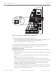


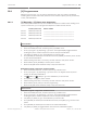
Table Of Contents
- Title Page
- Table of Contents
- Certifications, approvals, listings, and safety
- Introduction
- System overview
- Installation checklist
- Control panel installation
- Power supply
- Telephone communications
- IP communications
- Keypads, keyswitches, keyfobs and transmitters
- Keypads
- B915 Basic Keypad
- B920 Two-line Alphanumeric Keypad
- B921C Two-line Capacitive Keypad with Inputs
- B930 ATM Style Alphanumeric Keypad
- B942 Touch Screen Keypad
- Shortcuts and custom functions
- Address settings
- Supervision
- Installation and control panel wiring (keypads)
- Sensor loops overview and wiring (B921C/B942/B942W only)
- Output wiring (B942/B942W only)
- Troubleshooting
- Keyswitches
- RADION keyfobs and Inovonics pendant transmitters
- Keypads
- On-board outputs
- Off-board outputs
- On-board points
- Off-board points
- Wireless modules
- Access control
- Program and test the control panel
- Control panel board overview
- System wiring diagrams
- Approved applications
- Keypad Installer menu
- [1] Program menu
- [1] Reporting > [1] Phone menu parameters
- [1] Reporting > [2] Network menu parameters
- [1] Reporting > [3] Routing menu parameters
- [1] Reporting > [4] Personal Note menu parameters
- [2] Network > [1] Ethernet > (choose the bus module or on-board) > [1] Module Parameters menu
- [2] Network > [1] Ethernet > (choose the bus module or on-board) > [2] Address Parameters menu
- [2] Network > [1] Ethernet > (choose the bus module or on-board) > [3] DNS Parameters menu
- [2] Network > [2] Cellular > (choose the SDI2 cellular module or plug-in module)
- [3] RPS > [1] RPS Passcode menu parameters
- [3] RPS > [2] RPS Phone Number menu parameters
- [3] RPS > [3] RPS IP Address menu parameters
- [3] RPS > [4] RPS Port Number menu parameters
- [4] Area Options menu parameters
- [5] Keypad menu parameters
- [6] Users menu parameters
- [7] Points menu parameters
- [8] Disable Programming menu
- [2] Wireless menu
- [1] RF Point Menu> [1] Enroll Point RFID
- [1] RF Point Menu> [2] Replace Point RFID
- [1] RF Point Menu> [3] Remove Point RFID
- [2] RF Repeater Menu > [1] Add Repeater
- [2] RF Repeater Menu > [2] Replace Repeater
- [2] RF Repeater Menu > [3] Remove Repeater
- [3] RF Diagnostic Menu > [1] RF Points
- [3] RF Diagnostic Menu > [2] RF Repeater Menu
- [3] Diags menu
- [4] Serv Byp (Service Bypass) menu
- [5] Versions menu
- [6] Cloud menu
- [1] Program menu
- Specifications
- Appendix
- Back Page

7 COM 8
USB
ETHERNET
100BASE-T
LINK
1 k End of Line Resistors
Voltage Ranges
ON-BOARD POINTS
3.7 - 5.0 VDC
2.0 - 3.0 VDC
0.0 - 1.3 VDC
Open
Normal
Short
3 COM 4 5 COM 6
C
OUTPUT
B
TMPR
7 COM 83 COM 4 5 COM 6
RESET
ETHERNET
B C
OUTPUT
RESET
Figure 20.1: RESET button and Heartbeat LED location (B5512 shown)
Accessing SERVICE MODE (rapid pulsing Heartbeat LED):
1. Press and hold the control panel RESET button until the Heartbeat LED flashes fast. The
keypad shows SERVICE MODE and prompts for the installer passcode.
2. Enter your installer passcode and press [ENTER].
Exiting SERVICE MODE and returning to normal operation (slow pulsing Heartbeat LED):
Press and hold the control panel RESET button for approximately 5 seconds until the
Heartbeat LED turns off. The control panel resets.
Conventions for this section
This guide to the keypad Installer menu provides instructions for using the keypad, based on
the following conventions:
– All instructions access the Installer menu from the Main menu (Installer) option, not while
in Service mode.
– This section covers all compatible keypads. It provides specific steps for each keypad
style.
– Keys to press appear in this manual in brackets [ ].
– For simplicity, the keypad Installer menu tree and instructions combine the two-line
keypad number selections with the text and graphic steps of other keypads. For example,
rather than indicating that the two-line keypad reads Press [2] for enhanced comm
parameters, and that a different keypad reads Enhanced Comm Parms, this section
indicates the selection as [2] Enhanced Comm Parms.
– For simplicity and readability of instructions, this section lists menu steps in succession
with the > character separating steps. For example, Go to [1] Program > [1] Reporting >
[2] Network > [2] Enhanced Comm Parms.
104
en | Keypad Installer menu Control Panel
2016.05 | 14 | F.01U.287.180 Installation and System Reference Guide Bosch Security Systems, Inc.