
Installation Manual

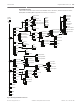


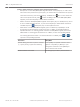
Table Of Contents
- Title Page
- Table of Contents
- Certifications, approvals, listings, and safety
- Introduction
- System overview
- Installation checklist
- Control panel installation
- Power supply
- Telephone communications
- IP communications
- Keypads, keyswitches, keyfobs and transmitters
- Keypads
- B915 Basic Keypad
- B920 Two-line Alphanumeric Keypad
- B921C Two-line Capacitive Keypad with Inputs
- B930 ATM Style Alphanumeric Keypad
- B942 Touch Screen Keypad
- Shortcuts and custom functions
- Address settings
- Supervision
- Installation and control panel wiring (keypads)
- Sensor loops overview and wiring (B921C/B942/B942W only)
- Output wiring (B942/B942W only)
- Troubleshooting
- Keyswitches
- RADION keyfobs and Inovonics pendant transmitters
- Keypads
- On-board outputs
- Off-board outputs
- On-board points
- Off-board points
- Wireless modules
- Access control
- Program and test the control panel
- Control panel board overview
- System wiring diagrams
- Approved applications
- Keypad Installer menu
- [1] Program menu
- [1] Reporting > [1] Phone menu parameters
- [1] Reporting > [2] Network menu parameters
- [1] Reporting > [3] Routing menu parameters
- [1] Reporting > [4] Personal Note menu parameters
- [2] Network > [1] Ethernet > (choose the bus module or on-board) > [1] Module Parameters menu
- [2] Network > [1] Ethernet > (choose the bus module or on-board) > [2] Address Parameters menu
- [2] Network > [1] Ethernet > (choose the bus module or on-board) > [3] DNS Parameters menu
- [2] Network > [2] Cellular > (choose the SDI2 cellular module or plug-in module)
- [3] RPS > [1] RPS Passcode menu parameters
- [3] RPS > [2] RPS Phone Number menu parameters
- [3] RPS > [3] RPS IP Address menu parameters
- [3] RPS > [4] RPS Port Number menu parameters
- [4] Area Options menu parameters
- [5] Keypad menu parameters
- [6] Users menu parameters
- [7] Points menu parameters
- [8] Disable Programming menu
- [2] Wireless menu
- [1] RF Point Menu> [1] Enroll Point RFID
- [1] RF Point Menu> [2] Replace Point RFID
- [1] RF Point Menu> [3] Remove Point RFID
- [2] RF Repeater Menu > [1] Add Repeater
- [2] RF Repeater Menu > [2] Replace Repeater
- [2] RF Repeater Menu > [3] Remove Repeater
- [3] RF Diagnostic Menu > [1] RF Points
- [3] RF Diagnostic Menu > [2] RF Repeater Menu
- [3] Diags menu
- [4] Serv Byp (Service Bypass) menu
- [5] Versions menu
- [6] Cloud menu
- [1] Program menu
- Specifications
- Appendix
- Back Page

Keypad menu trees
This section includes menu trees for the Installer menu structure, and the structures of the
B93x/B94x and B91x/B92x keypads user menus, for reference.
RF point diag
Diags
menu
Wireless
menu
Installer
menu
Areas
RPS
Reporting
Network
Keypad
1
Users
1
2
3
5
6
4
2
Installer
passcode
3
4
Srvc Byp menu
5
ESC
Exit
Program
menu
1
Points
7
Disable
8
ESC Exit
Phone
Network
Routing
Notification
2
3
4
1
Enhanced Comm
Enhanced Comm Parms
2
1
Exit Reporting menu
ESC
Format
AES Size
AES Entry
Exit
ESC
Phone Number
Format
Exit menu
ESC
ESC Exit
Primary
Backup
Exit menu
ESC
Ethernet
Cellular
2
1
ESC Exit
Module Parameters
Address Parameters
2
1
ESC
RPS Passcode
RPS Phone Number
RPS IP Address
RPS Port Number
2
3
4
1
ESC Exit
Area On
Account #
Exit menu
ESC
Exit
ESC
Index
Source
Exit menu
ESC
RF Point Menu
RF Repeater Menu
2
3
1
ESC Exit
RF Diagnostic Menu
Enroll point RFID
Replace point RFID
2
3
1
ESC Exit
Remove point RFID
Add repeater
Replace repeater
ESC Exit
Remove repeater
1
RF repeater diag
2
1
Exit
ESC
RF point state
RF point signal
2
1
Exit
ESC
RF repeater state
RF repeater signal
2
Exit
ESC
Wireless
Network
2
1
DNS Parameters
Scope
DHCP Enable
UPnP Enable
2
1
Exit menu
ESC
3
IP Address
Subnet Mask
2
1
Exit menu
ESC
Default Gateway
3
Port Number
4
IPv4 Server Address
IPv6 Server Address
2
1
Exit
ESC
Module Hostname
3
2
3
1
Versions menu
ESC
Cellular
IP Camera4
3
Settings
Connection
2
1
Exit
ESC
SDI2 Cellular (1)
SDI2 Cellular (2)
2
1
ESC
Bus Module (1)
On-board
3
1
Exit
ESC
SDI2 Cellular (1)
Plug-in Module
3
1
Exit
ESC
SIM APN
SIM Username
SIM Passcode
SIM PIN
2
3
4
1
ESC Exit
Bus Module (2)
2
Type
Plug-in Module3
SDI2 Cellular (2)
2
Bus Module (1)
On-board IP
3
1
Exit
ESC
Bus Module (2)2
Address
Port #
Poll Rate
Cloud5
6
Cloud menu
Figure 20.2: Keypad installer menu tree
Control Panel Keypad Installer menu | en 105
Bosch Security Systems, Inc. Installation and System Reference Guide 2016.05 | 14 | F.01U.287.180