
Installation Manual

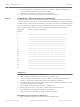


Table Of Contents
- Title Page
- Table of Contents
- Certifications, approvals, listings, and safety
- Introduction
- System overview
- Installation checklist
- Control panel installation
- Power supply
- Telephone communications
- IP communications
- Keypads, keyswitches, keyfobs and transmitters
- Keypads
- B915 Basic Keypad
- B920 Two-line Alphanumeric Keypad
- B921C Two-line Capacitive Keypad with Inputs
- B930 ATM Style Alphanumeric Keypad
- B942 Touch Screen Keypad
- Shortcuts and custom functions
- Address settings
- Supervision
- Installation and control panel wiring (keypads)
- Sensor loops overview and wiring (B921C/B942/B942W only)
- Output wiring (B942/B942W only)
- Troubleshooting
- Keyswitches
- RADION keyfobs and Inovonics pendant transmitters
- Keypads
- On-board outputs
- Off-board outputs
- On-board points
- Off-board points
- Wireless modules
- Access control
- Program and test the control panel
- Control panel board overview
- System wiring diagrams
- Approved applications
- Keypad Installer menu
- [1] Program menu
- [1] Reporting > [1] Phone menu parameters
- [1] Reporting > [2] Network menu parameters
- [1] Reporting > [3] Routing menu parameters
- [1] Reporting > [4] Personal Note menu parameters
- [2] Network > [1] Ethernet > (choose the bus module or on-board) > [1] Module Parameters menu
- [2] Network > [1] Ethernet > (choose the bus module or on-board) > [2] Address Parameters menu
- [2] Network > [1] Ethernet > (choose the bus module or on-board) > [3] DNS Parameters menu
- [2] Network > [2] Cellular > (choose the SDI2 cellular module or plug-in module)
- [3] RPS > [1] RPS Passcode menu parameters
- [3] RPS > [2] RPS Phone Number menu parameters
- [3] RPS > [3] RPS IP Address menu parameters
- [3] RPS > [4] RPS Port Number menu parameters
- [4] Area Options menu parameters
- [5] Keypad menu parameters
- [6] Users menu parameters
- [7] Points menu parameters
- [8] Disable Programming menu
- [2] Wireless menu
- [1] RF Point Menu> [1] Enroll Point RFID
- [1] RF Point Menu> [2] Replace Point RFID
- [1] RF Point Menu> [3] Remove Point RFID
- [2] RF Repeater Menu > [1] Add Repeater
- [2] RF Repeater Menu > [2] Replace Repeater
- [2] RF Repeater Menu > [3] Remove Repeater
- [3] RF Diagnostic Menu > [1] RF Points
- [3] RF Diagnostic Menu > [2] RF Repeater Menu
- [3] Diags menu
- [4] Serv Byp (Service Bypass) menu
- [5] Versions menu
- [6] Cloud menu
- [1] Program menu
- Specifications
- Appendix
- Back Page

4. Press [Edit] to change the network address. The existing address and an editing cursor
show.
5. Delete existing characters, if necessary, and then enter the new address.
6. Press [Save] to save the address. The keypad shows Parameter Saved, and returns to the
previous menu.
7. Press [Port #] to view the port number, and then press [Edit] to edit the port number.
8. Delete existing characters, if necessary, and then enter the new port number.
9. Press [Save] to save the address. The keypad shows Parameter Saved, and returns to the
previous menu.
10. Press [Poll Rate] to view the poll rate, and then press [Edit] to edit the poll rate number.
11. Delete existing characters, if necessary, and then enter the new poll rate.
12. Press [Save] to save the address. The keypad shows Parameter Saved, and returns to the
previous menu.
13. Press the icon or softkey for the desired option (address, port #, poll rate, AES key size).
14. Press [Edit] to change programming.
15. Press [Save] to save the programming.
16. When the keypad shows Parameter Saved, escape from the menu.
[1] Reporting > [3] Routing menu parameters
Use routing to program primary and backup destinations over standard telephone lines, local
area network (LAN) or wide area network (WAN). In this menu, you can designate the primary
and backup destinations for up to four routes.
Options include:
No Device, Phone 1, Phone 2, Phone 3, Phone 4, SDI2-1 D1, SDI2-1 D2, SDI2-1 D3, SDI2-1 D4,
SDI2-2 D1, SDI2-2 D2, SDI2-2 D3, SDI2-2 D4, Onboard D1, Onboard D2, Onboard D3, Onboard
D4, Cellular D1, Cellular D2, Cellular D3, Cellular D4.
Route 1 Route 2 Route 3 Route 4
Primary Device No Device ___________ ___________ ___________ ___________
Backup Device No Device ___________ ___________ ___________ ___________
Primary Destination Device
B91x/B92x keypads configuration of Primary Destination Device
1. Enter the installer passcode, and then open the [1] Installer menu.
2. Go to [1] Program > [1] Reporting > [3] Routing. The keypad toggles between showing
the current primary and backup setting for the selected route.
3. Use [PREV] or NEXT] to scroll though the list of routes and go to the route you want to
program.
4. Press [ENTER] to edit the route.
5. Press [ENTER] to edit the primary route. The keypad shows Set Route Device.
6. Use [PREV] or NEXT] to scroll though the list of devices (for destination 1) and go to the
destination 1 option you want to select for the current device (for example, Phone 1).
7. Press [ENTER] to select the device. The keypad shows Set route dest 1-4. To keep
destination 1, escape from the menu. To change to a different destination (2, 3, or 4),
continue to Step 8.
8. Delete existing characters, if necessary, and then enter the new number.
9. Press [ENTER] to save the change, and then escape from the menu.
20.1.3
112 en | Keypad Installer menu Control Panel
2016.05 | 14 | F.01U.287.180 Installation and System Reference Guide Bosch Security Systems, Inc.