
Installation Manual


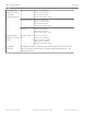

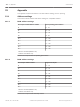
Table Of Contents
- Title Page
- Table of Contents
- Certifications, approvals, listings, and safety
- Introduction
- System overview
- Installation checklist
- Control panel installation
- Power supply
- Telephone communications
- IP communications
- Keypads, keyswitches, keyfobs and transmitters
- Keypads
- B915 Basic Keypad
- B920 Two-line Alphanumeric Keypad
- B921C Two-line Capacitive Keypad with Inputs
- B930 ATM Style Alphanumeric Keypad
- B942 Touch Screen Keypad
- Shortcuts and custom functions
- Address settings
- Supervision
- Installation and control panel wiring (keypads)
- Sensor loops overview and wiring (B921C/B942/B942W only)
- Output wiring (B942/B942W only)
- Troubleshooting
- Keyswitches
- RADION keyfobs and Inovonics pendant transmitters
- Keypads
- On-board outputs
- Off-board outputs
- On-board points
- Off-board points
- Wireless modules
- Access control
- Program and test the control panel
- Control panel board overview
- System wiring diagrams
- Approved applications
- Keypad Installer menu
- [1] Program menu
- [1] Reporting > [1] Phone menu parameters
- [1] Reporting > [2] Network menu parameters
- [1] Reporting > [3] Routing menu parameters
- [1] Reporting > [4] Personal Note menu parameters
- [2] Network > [1] Ethernet > (choose the bus module or on-board) > [1] Module Parameters menu
- [2] Network > [1] Ethernet > (choose the bus module or on-board) > [2] Address Parameters menu
- [2] Network > [1] Ethernet > (choose the bus module or on-board) > [3] DNS Parameters menu
- [2] Network > [2] Cellular > (choose the SDI2 cellular module or plug-in module)
- [3] RPS > [1] RPS Passcode menu parameters
- [3] RPS > [2] RPS Phone Number menu parameters
- [3] RPS > [3] RPS IP Address menu parameters
- [3] RPS > [4] RPS Port Number menu parameters
- [4] Area Options menu parameters
- [5] Keypad menu parameters
- [6] Users menu parameters
- [7] Points menu parameters
- [8] Disable Programming menu
- [2] Wireless menu
- [1] RF Point Menu> [1] Enroll Point RFID
- [1] RF Point Menu> [2] Replace Point RFID
- [1] RF Point Menu> [3] Remove Point RFID
- [2] RF Repeater Menu > [1] Add Repeater
- [2] RF Repeater Menu > [2] Replace Repeater
- [2] RF Repeater Menu > [3] Remove Repeater
- [3] RF Diagnostic Menu > [1] RF Points
- [3] RF Diagnostic Menu > [2] RF Repeater Menu
- [3] Diags menu
- [4] Serv Byp (Service Bypass) menu
- [5] Versions menu
- [6] Cloud menu
- [1] Program menu
- Specifications
- Appendix
- Back Page

B93x/B94x keypads use of Connection (for the Bus Module)
1. Enter the installer passcode, and then open the [1] Installer menu.
2. Go to [2] Network > (choose the bus module or on-board) > [2] Connection. The keypad
scrolls through the following sub-categories, indicating the diagnostic information for:
Link, IP Address, DNS, WAN IPv4, WAN IPv6, LAN IPv4, LAN IPv6.
3. When finished viewing the information, escape from the menu.
[3] Cellular menu
You can obtain certain cellular module diagnostic information using a keypad and this menu.
Cellular (diagnostics)
B91x/B92x keypads use of Cellular (diagnostics)
1. Enter the installer passcode, and then open the [1] Installer menu.
2. Go to [3] Diags Menu > [3] Cellular > (choose the SDI2 cellular module or plug-in
module). The keypad scrolls through the following sub-categories, indicating the
diagnostic information for:
– Link (Yes or No. Yes indicates a data connection to the carrier. No indicates a
connection problem.)
– iPv4 IP (The IP address of the cellular radio on the carrier’s network.)
– Base ID
– Signal (Signal strength = unacceptable, marginal, good, or very good.)
– Signal (In dBs.)
– Tel Num (If provided by the carrier.)
– ESN (The cellular radio electronic serial number.)
– Model (The cellular radio model.)
– Version (The cellular radio version.)
3. When finished viewing the information, escape from the menu.
B93x/B94x keypads use of Cellular (diagnostics)
1. Enter the installer passcode, and then open the [1] Installer menu.
2. Go to [3] Diags Menu > [3] Cellular > (choose the SDI2 cellular module or plug-in
module). The keypad scrolls through the following sub-categories, indicating the
diagnostic information for:
– Link (Yes or No. Yes indicates a data connection to the carrier. No indicates a
connection problem.)
– iPv4 IP (The IP address of the cellular radio on the carrier’s network.)
– Base ID
– Signal (Signal strength = unacceptable, marginal, good, or very good.)
– Signal (In dBs.)
– Tel Num (If provided by the carrier.)
– ESN (The cellular radio electronic serial number.)
– Model (The cellular radio model.)
– Version (The cellular radio version.)
3. When finished viewing the information, escape from the menu.
[4] IP Camera
IP Camera
20.3.3
20.3.4
142 en | Keypad Installer menu Control Panel
2016.05 | 14 | F.01U.287.180 Installation and System Reference Guide Bosch Security Systems, Inc.