
Installation Manual


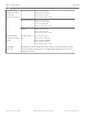

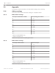
Table Of Contents
- Title Page
- Table of Contents
- Certifications, approvals, listings, and safety
- Introduction
- System overview
- Installation checklist
- Control panel installation
- Power supply
- Telephone communications
- IP communications
- Keypads, keyswitches, keyfobs and transmitters
- Keypads
- B915 Basic Keypad
- B920 Two-line Alphanumeric Keypad
- B921C Two-line Capacitive Keypad with Inputs
- B930 ATM Style Alphanumeric Keypad
- B942 Touch Screen Keypad
- Shortcuts and custom functions
- Address settings
- Supervision
- Installation and control panel wiring (keypads)
- Sensor loops overview and wiring (B921C/B942/B942W only)
- Output wiring (B942/B942W only)
- Troubleshooting
- Keyswitches
- RADION keyfobs and Inovonics pendant transmitters
- Keypads
- On-board outputs
- Off-board outputs
- On-board points
- Off-board points
- Wireless modules
- Access control
- Program and test the control panel
- Control panel board overview
- System wiring diagrams
- Approved applications
- Keypad Installer menu
- [1] Program menu
- [1] Reporting > [1] Phone menu parameters
- [1] Reporting > [2] Network menu parameters
- [1] Reporting > [3] Routing menu parameters
- [1] Reporting > [4] Personal Note menu parameters
- [2] Network > [1] Ethernet > (choose the bus module or on-board) > [1] Module Parameters menu
- [2] Network > [1] Ethernet > (choose the bus module or on-board) > [2] Address Parameters menu
- [2] Network > [1] Ethernet > (choose the bus module or on-board) > [3] DNS Parameters menu
- [2] Network > [2] Cellular > (choose the SDI2 cellular module or plug-in module)
- [3] RPS > [1] RPS Passcode menu parameters
- [3] RPS > [2] RPS Phone Number menu parameters
- [3] RPS > [3] RPS IP Address menu parameters
- [3] RPS > [4] RPS Port Number menu parameters
- [4] Area Options menu parameters
- [5] Keypad menu parameters
- [6] Users menu parameters
- [7] Points menu parameters
- [8] Disable Programming menu
- [2] Wireless menu
- [1] RF Point Menu> [1] Enroll Point RFID
- [1] RF Point Menu> [2] Replace Point RFID
- [1] RF Point Menu> [3] Remove Point RFID
- [2] RF Repeater Menu > [1] Add Repeater
- [2] RF Repeater Menu > [2] Replace Repeater
- [2] RF Repeater Menu > [3] Remove Repeater
- [3] RF Diagnostic Menu > [1] RF Points
- [3] RF Diagnostic Menu > [2] RF Repeater Menu
- [3] Diags menu
- [4] Serv Byp (Service Bypass) menu
- [5] Versions menu
- [6] Cloud menu
- [1] Program menu
- Specifications
- Appendix
- Back Page

Specifications
Control panel power supply specifications
Voltage input (power
supply)
Primary 18 VAC
terminals
18 VAC 22 VA Class 2 transformer (CX4010)
Secondary BAT terminals 12 Volt Sealed Lead Acid Rechargeable Battery (D126
or D1218)
Current
requirements
Control Panel: Idle 125 mA; Alarm 155 mA
Refer to the Standby battery requirements and calculations section in the control
panel Installation and System Reference Guide (this document) for the current draw
requirements of other system components.
Power outputs All external connections are power-limited. The battery terminals are not power
limited.
SDI2 terminals and
interconnect
connector
PWR/R and
COM/B
terminals
800 mA for continuously powered devices.
Shared with AUX power terminal.
Alarm power
output
OUTPUT A
terminal
1.3 A for Burglary applications. Output can be
steady or one of four pulsed patterns depending
on programming. Refer to Outputs in RPS Help or
the control panel Program Entry Guide.
Aux power AUX and
COM
terminals
800 mA for continuously powered devices.
Shared with SDI2 R/PWR terminal and
interconnect connector.
Fire and Fire/
Burglary Systems
Alarm power output for OUTPUT A cannot exceed 500 mA.
Minimum operating
voltage
10.2 VDC (The control panel might operate below this voltage, but it will cease to
operate as an alarm panel.)
SDI2 bus 12 VDC nominal (7500 ft combined length) maximum
Ethernet connection
(optional)
10BASE-T
100BASE-TX
Battery discharge/
recharge schedule
Discharge cycle 13.65 VDC - Charging float level.
12.1 VDC - Low Battery Report, if programmed.
10.2 VDC - Minimum operational voltage.
Recharge Cycle AC ON - Battery charging begins and AC Restoral Reports sent.
13.4 V - Battery Restoral Report sent. Battery float charged.
Environmental Temperature 0℃ to +49℃ (+32℉ to 122℉)
Relative Humidity 5% to 93% at +32℃ (+90℉) non-condensing
Arming stations B915/B915IBasic Keypads, B920 Two-line Alphanumeric Keypads (SDI2), B921C
Two-line Alphanumeric Keypads (SDI2), B930 ATM Style Alphanumeric Keypads
(SDI2), B942/B942W Touch Screen keypads
21
Control Panel Specifications | en 147
Bosch Security Systems, Inc. Installation and System Reference Guide 2016.05 | 14 | F.01U.287.180