
Installation Manual


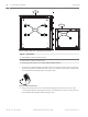
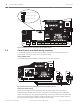

Table Of Contents
- Title Page
- Table of Contents
- Certifications, approvals, listings, and safety
- Introduction
- System overview
- Installation checklist
- Control panel installation
- Power supply
- Telephone communications
- IP communications
- Keypads, keyswitches, keyfobs and transmitters
- Keypads
- B915 Basic Keypad
- B920 Two-line Alphanumeric Keypad
- B921C Two-line Capacitive Keypad with Inputs
- B930 ATM Style Alphanumeric Keypad
- B942 Touch Screen Keypad
- Shortcuts and custom functions
- Address settings
- Supervision
- Installation and control panel wiring (keypads)
- Sensor loops overview and wiring (B921C/B942/B942W only)
- Output wiring (B942/B942W only)
- Troubleshooting
- Keyswitches
- RADION keyfobs and Inovonics pendant transmitters
- Keypads
- On-board outputs
- Off-board outputs
- On-board points
- Off-board points
- Wireless modules
- Access control
- Program and test the control panel
- Control panel board overview
- System wiring diagrams
- Approved applications
- Keypad Installer menu
- [1] Program menu
- [1] Reporting > [1] Phone menu parameters
- [1] Reporting > [2] Network menu parameters
- [1] Reporting > [3] Routing menu parameters
- [1] Reporting > [4] Personal Note menu parameters
- [2] Network > [1] Ethernet > (choose the bus module or on-board) > [1] Module Parameters menu
- [2] Network > [1] Ethernet > (choose the bus module or on-board) > [2] Address Parameters menu
- [2] Network > [1] Ethernet > (choose the bus module or on-board) > [3] DNS Parameters menu
- [2] Network > [2] Cellular > (choose the SDI2 cellular module or plug-in module)
- [3] RPS > [1] RPS Passcode menu parameters
- [3] RPS > [2] RPS Phone Number menu parameters
- [3] RPS > [3] RPS IP Address menu parameters
- [3] RPS > [4] RPS Port Number menu parameters
- [4] Area Options menu parameters
- [5] Keypad menu parameters
- [6] Users menu parameters
- [7] Points menu parameters
- [8] Disable Programming menu
- [2] Wireless menu
- [1] RF Point Menu> [1] Enroll Point RFID
- [1] RF Point Menu> [2] Replace Point RFID
- [1] RF Point Menu> [3] Remove Point RFID
- [2] RF Repeater Menu > [1] Add Repeater
- [2] RF Repeater Menu > [2] Replace Repeater
- [2] RF Repeater Menu > [3] Remove Repeater
- [3] RF Diagnostic Menu > [1] RF Points
- [3] RF Diagnostic Menu > [2] RF Repeater Menu
- [3] Diags menu
- [4] Serv Byp (Service Bypass) menu
- [5] Versions menu
- [6] Cloud menu
- [1] Program menu
- Specifications
- Appendix
- Back Page

In each of the examples above, all of the areas are under the sole responsibility of a single
owner.
In multi-area systems, the bell (or siren) and control panel must be in one of the protected
areas.
The bell or siren must be located where it can be heard by users who turn areas on and off
(arm and disarm).
Digital communication
The control panel uses its built-in Ethernet connection, a B426 Conettix Ethernet
Communication Module, a Conettix Plug-in cellular module (B440/B441/B442/B443 plugged
into the control panel or plugged into a B450 Conettix Plug-in Communicator Interface), or a
B430 Plug-in Telephone Communicator to send reports to the central station receiver.
The control panel sends reports in either the Modem4 or ANSI-SIA Contact ID format.
The system can route Event Reports to four different destinations through an IP network or
the telephone network (PSTN). Program primary and backup reporting destinations for each.
A custom option allows you to specify which Event Reports the system sends.
Keypads
B5512/B4512 control panels support up to 8 keypads, in any combination of SDI2 keypad
models. The B3512 supports up to 4 keypads.
The control panel supervises all SDI2 keypads. Supervision for the 16 SDI keypads is
configurable.
Events
Event memory
The control panel retains point alarm and trouble events for each area in event memory. You
can view event memory on a keypad. Turning an area on clears the event memory for that area.
Event log
The event log stores local and reported events. The event log includes information such as
time, date, event, area, point, and user. View the event log from a keypad or use RPS to
remotely retrieve event information. When the event log reaches a programmed threshold of
stored events, it can send an optional report to a receiver.
B5512 control panels store up to 255 events. B4512 and B3512 control panels store up to
127.
Programming
Use RPS to program the control panels. You can connect to the control panel using a network
connection (on-board Ethernet port, cellular module, B426 Conettix Ethernet Communication
Module, or telephone module), or locally using the control panel’s on-board Ethernet port or
USB port. (To program with the USB port connection, use the B99 USB 2.0 Type A Male to
Type A Male cable by Bosch.) You can also use a keypad for select programming.
Refer to RPS Help or the control panel's Program Entry Guide, and to Keypad Installer menu,
page 103 for programming options.
Notice!
After system installation and any control panel programming, perform a complete system test.
A complete system test includes testing the control panel, all devices, and communication
destinations for proper operation.
3.3.4
3.3.5
3.3.6
3.3.7
Control Panel System overview | en 21
Bosch Security Systems, Inc. Installation and System Reference Guide 2016.05 | 14 | F.01U.287.180