
Installation Manual


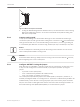
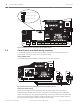

Table Of Contents
- Title Page
- Table of Contents
- Certifications, approvals, listings, and safety
- Introduction
- System overview
- Installation checklist
- Control panel installation
- Power supply
- Telephone communications
- IP communications
- Keypads, keyswitches, keyfobs and transmitters
- Keypads
- B915 Basic Keypad
- B920 Two-line Alphanumeric Keypad
- B921C Two-line Capacitive Keypad with Inputs
- B930 ATM Style Alphanumeric Keypad
- B942 Touch Screen Keypad
- Shortcuts and custom functions
- Address settings
- Supervision
- Installation and control panel wiring (keypads)
- Sensor loops overview and wiring (B921C/B942/B942W only)
- Output wiring (B942/B942W only)
- Troubleshooting
- Keyswitches
- RADION keyfobs and Inovonics pendant transmitters
- Keypads
- On-board outputs
- Off-board outputs
- On-board points
- Off-board points
- Wireless modules
- Access control
- Program and test the control panel
- Control panel board overview
- System wiring diagrams
- Approved applications
- Keypad Installer menu
- [1] Program menu
- [1] Reporting > [1] Phone menu parameters
- [1] Reporting > [2] Network menu parameters
- [1] Reporting > [3] Routing menu parameters
- [1] Reporting > [4] Personal Note menu parameters
- [2] Network > [1] Ethernet > (choose the bus module or on-board) > [1] Module Parameters menu
- [2] Network > [1] Ethernet > (choose the bus module or on-board) > [2] Address Parameters menu
- [2] Network > [1] Ethernet > (choose the bus module or on-board) > [3] DNS Parameters menu
- [2] Network > [2] Cellular > (choose the SDI2 cellular module or plug-in module)
- [3] RPS > [1] RPS Passcode menu parameters
- [3] RPS > [2] RPS Phone Number menu parameters
- [3] RPS > [3] RPS IP Address menu parameters
- [3] RPS > [4] RPS Port Number menu parameters
- [4] Area Options menu parameters
- [5] Keypad menu parameters
- [6] Users menu parameters
- [7] Points menu parameters
- [8] Disable Programming menu
- [2] Wireless menu
- [1] RF Point Menu> [1] Enroll Point RFID
- [1] RF Point Menu> [2] Replace Point RFID
- [1] RF Point Menu> [3] Remove Point RFID
- [2] RF Repeater Menu > [1] Add Repeater
- [2] RF Repeater Menu > [2] Replace Repeater
- [2] RF Repeater Menu > [3] Remove Repeater
- [3] RF Diagnostic Menu > [1] RF Points
- [3] RF Diagnostic Menu > [2] RF Repeater Menu
- [3] Diags menu
- [4] Serv Byp (Service Bypass) menu
- [5] Versions menu
- [6] Cloud menu
- [1] Program menu
- Specifications
- Appendix
- Back Page

Figure 5.4: Mount control panel on standoffs
4. If using the B12 Mounting Plate for D8103 Enclosure, rest the hook tabs on the mounting
plate hooks within the enclosure. Secure the lock-down tab to the plate mounting hole
with the screw provided.
Connect earth ground
To help prevent damage from electrostatic discharges or other transient electrical surges,
connect the system to earth ground before making other connections. The icon indicates the
earth ground terminal. Use a recommended earth ground reference, such as a grounding rod
or a cold water pipe. Make the connection using 14 AWG (1.8 mm) to 16 AWG (1.5 mm) wire.
Notice!
Do not use telephone or electrical ground for the earth ground connection. Do not connect
other control panel terminals to earth ground.
!
Caution!
Avoid electrostatic discharge. Always touch the earth ground connection with the icon first,
before beginning work on the control panel.
Configure OUTPUT A using the jumper
When planning your installation, carefully consider the use of OUTPUT A. OUTPUT A is a form
C relay. You can configure the common terminal (C) of Output A (OUTPUT A) using the
jumper:
– To provide +12 VDC (AUX power)
– To be a COM terminal (parallel to all COM terminals)
– To be a dry contact (no voltage, not common)
The control panel ships with the jumper in the default position, AUX power. (OUTPUT A, ‘C’
terminal providing AUX PWR). To reconfigure the ‘C’ terminal as a COM terminal (parallel to all
COM terminals), remove the door covering the jumper pins, and move the jumper to the left
two pins. The OUTPUT A LED lights when OUTPUT A is active. Refer to the figure below or to
the Enclosure Wiring Label (B5512/B4512/B3512) to set the OUTPUT A jumper.
5.2.2
5.2.3
Control Panel Control panel installation | en 27
Bosch Security Systems, Inc. Installation and System Reference Guide 2016.05 | 14 | F.01U.287.180