
Installation Manual


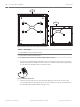
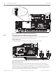

Table Of Contents
- Title Page
- Table of Contents
- Certifications, approvals, listings, and safety
- Introduction
- System overview
- Installation checklist
- Control panel installation
- Power supply
- Telephone communications
- IP communications
- Keypads, keyswitches, keyfobs and transmitters
- Keypads
- B915 Basic Keypad
- B920 Two-line Alphanumeric Keypad
- B921C Two-line Capacitive Keypad with Inputs
- B930 ATM Style Alphanumeric Keypad
- B942 Touch Screen Keypad
- Shortcuts and custom functions
- Address settings
- Supervision
- Installation and control panel wiring (keypads)
- Sensor loops overview and wiring (B921C/B942/B942W only)
- Output wiring (B942/B942W only)
- Troubleshooting
- Keyswitches
- RADION keyfobs and Inovonics pendant transmitters
- Keypads
- On-board outputs
- Off-board outputs
- On-board points
- Off-board points
- Wireless modules
- Access control
- Program and test the control panel
- Control panel board overview
- System wiring diagrams
- Approved applications
- Keypad Installer menu
- [1] Program menu
- [1] Reporting > [1] Phone menu parameters
- [1] Reporting > [2] Network menu parameters
- [1] Reporting > [3] Routing menu parameters
- [1] Reporting > [4] Personal Note menu parameters
- [2] Network > [1] Ethernet > (choose the bus module or on-board) > [1] Module Parameters menu
- [2] Network > [1] Ethernet > (choose the bus module or on-board) > [2] Address Parameters menu
- [2] Network > [1] Ethernet > (choose the bus module or on-board) > [3] DNS Parameters menu
- [2] Network > [2] Cellular > (choose the SDI2 cellular module or plug-in module)
- [3] RPS > [1] RPS Passcode menu parameters
- [3] RPS > [2] RPS Phone Number menu parameters
- [3] RPS > [3] RPS IP Address menu parameters
- [3] RPS > [4] RPS Port Number menu parameters
- [4] Area Options menu parameters
- [5] Keypad menu parameters
- [6] Users menu parameters
- [7] Points menu parameters
- [8] Disable Programming menu
- [2] Wireless menu
- [1] RF Point Menu> [1] Enroll Point RFID
- [1] RF Point Menu> [2] Replace Point RFID
- [1] RF Point Menu> [3] Remove Point RFID
- [2] RF Repeater Menu > [1] Add Repeater
- [2] RF Repeater Menu > [2] Replace Repeater
- [2] RF Repeater Menu > [3] Remove Repeater
- [3] RF Diagnostic Menu > [1] RF Points
- [3] RF Diagnostic Menu > [2] RF Repeater Menu
- [3] Diags menu
- [4] Serv Byp (Service Bypass) menu
- [5] Versions menu
- [6] Cloud menu
- [1] Program menu
- Specifications
- Appendix
- Back Page

Power supply
This section provides information on installing and maintaining primary power, batteries, and
auxiliary power.
Primary (AC) power
The control panel uses an 18 VAC, 22 VA internally fused transformer (CX4010) for its primary
power source. The control panel draws 125 mA when idle and 155 mA when in the alarm
state. The auxiliary power available for powered devices is 800 mA.
Surge protection
Transient suppressors and spark gaps protect the circuit from power surges. This protection
relies on the ground connection at the earth ground terminal , marked with the
icon. Ensure
that you connect the terminal to a proper ground.
Refer to Connect earth ground, page 27.
AC power fail
The system indicates an AC power failure when the VAC terminals do not have sufficient
voltage. The AC Fail Time parameter sets the amount of time without AC power before the
control panel reports the failure, and the amount of time after the power returns before the
control panel reports restored power.
Self diagnostics at power up and reset
The system performs a series of self-diagnostic tests of hardware, software, and programming
at power up and at reset. The self-diagnostics tests complete in approximately 10 to 30 sec.
If the control panel fails any test, a System Trouble message appears at the keypads.
Install the transformer
!
Caution!
Do not short-circuit the terminals of the transformer: Shorting the terminals opens the
internal fuse, causing permanent failure. Connect the transformer to the control panel's AC
power terminals before plugging it into the power source.
Notice!
Plan ahead
Route telephone, SDI2 bus wiring, and sensor loop wiring away from any AC conductors,
including the transformer wire. AC wiring can induce noise and low level voltage into adjacent
wiring.
1. Use 18 AWG (1.02 mm) wire minimum (12 AWG [2 mm] maximum) and connect the
transformer to the control panel. Make the wire length as short as possible. Do not
exceed 50 ft (15 m).
2. Connect the wire to the control panel.
3. Connect the wire to the transformer.
4. Plug the transformer into an unswitched, 120 VAC, 60 Hz power outlet only.
5. Secure the transformer to the outlet with the screw provided (not applicable in
Cananda).
Secondary (DC) power
6
6.1
6.1.1
6.2
30 en | Power supply Control Panel
2016.05 | 14 | F.01U.287.180 Installation and System Reference Guide Bosch Security Systems, Inc.