
Installation Manual

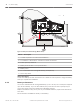

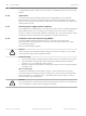

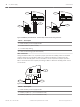

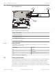


Table Of Contents
- Title Page
- Table of Contents
- Certifications, approvals, listings, and safety
- Introduction
- System overview
- Installation checklist
- Control panel installation
- Power supply
- Telephone communications
- IP communications
- Keypads, keyswitches, keyfobs and transmitters
- Keypads
- B915 Basic Keypad
- B920 Two-line Alphanumeric Keypad
- B921C Two-line Capacitive Keypad with Inputs
- B930 ATM Style Alphanumeric Keypad
- B942 Touch Screen Keypad
- Shortcuts and custom functions
- Address settings
- Supervision
- Installation and control panel wiring (keypads)
- Sensor loops overview and wiring (B921C/B942/B942W only)
- Output wiring (B942/B942W only)
- Troubleshooting
- Keyswitches
- RADION keyfobs and Inovonics pendant transmitters
- Keypads
- On-board outputs
- Off-board outputs
- On-board points
- Off-board points
- Wireless modules
- Access control
- Program and test the control panel
- Control panel board overview
- System wiring diagrams
- Approved applications
- Keypad Installer menu
- [1] Program menu
- [1] Reporting > [1] Phone menu parameters
- [1] Reporting > [2] Network menu parameters
- [1] Reporting > [3] Routing menu parameters
- [1] Reporting > [4] Personal Note menu parameters
- [2] Network > [1] Ethernet > (choose the bus module or on-board) > [1] Module Parameters menu
- [2] Network > [1] Ethernet > (choose the bus module or on-board) > [2] Address Parameters menu
- [2] Network > [1] Ethernet > (choose the bus module or on-board) > [3] DNS Parameters menu
- [2] Network > [2] Cellular > (choose the SDI2 cellular module or plug-in module)
- [3] RPS > [1] RPS Passcode menu parameters
- [3] RPS > [2] RPS Phone Number menu parameters
- [3] RPS > [3] RPS IP Address menu parameters
- [3] RPS > [4] RPS Port Number menu parameters
- [4] Area Options menu parameters
- [5] Keypad menu parameters
- [6] Users menu parameters
- [7] Points menu parameters
- [8] Disable Programming menu
- [2] Wireless menu
- [1] RF Point Menu> [1] Enroll Point RFID
- [1] RF Point Menu> [2] Replace Point RFID
- [1] RF Point Menu> [3] Remove Point RFID
- [2] RF Repeater Menu > [1] Add Repeater
- [2] RF Repeater Menu > [2] Replace Repeater
- [2] RF Repeater Menu > [3] Remove Repeater
- [3] RF Diagnostic Menu > [1] RF Points
- [3] RF Diagnostic Menu > [2] RF Repeater Menu
- [3] Diags menu
- [4] Serv Byp (Service Bypass) menu
- [5] Versions menu
- [6] Cloud menu
- [1] Program menu
- Specifications
- Appendix
- Back Page

1
2
3
4
5
6
7
TMPR
1 COM 2 7 COM 83 COM 4 5 COM 6
RESET
ETHERNET
COM AUX
R Y G B
PWR A B COM
+ BAT -
18VAC
B C
OUTPUT
NO C NC
OUTPUT A
7 COM 8
C
OUTPUT
B
USB
ETHERNET
100BASE-T
LINK
COMMUNICATION MODULE 1
1 k End of Line Resistors
Voltage Ranges
ON-BOARD POINTS
3.7 - 5.0 VDC
2.0 - 3.0 VDC
0.0 - 1.3 VDC
Open
Normal
Short
3 COM 4 5 COM 61 COM 2
R Y G B
SDI2
Device Bus
18 VAC
BATTERY OUTPUT A
AUX
- 12 V +
OUTPUT A
OUTPUT A
Jumper Under Cover
AUX PWR
COM
DRY
Figure 6.1: Non-power-limited wiring (B5512 shown)
Callout ᅳ Description
1 ᅳ Conduit required for use with external batteries
2 ᅳ To CX4010 UL Listed Class 2 Transformer 18 VAC 22 VA 60 Hz
3 ᅳ 0.25 in (6.4 mm) minimum
4 ᅳ Battery terminals. BAT- is non-power limited
5 ᅳ Battery wires
6 ᅳ 12 V sealed lead-acid rechargeable battery (D126/D1218)
7 ᅳ Sensor loop wires
Charge the battery
Connect the battery and then the transformer to allow the control panel to charge the battery
while you complete the installation.
Battery maintenance
Use 12 VDC sealed lead-acid rechargeable battery (7 Ah or 18 Ah). The control panel supports
up to 18 Ah of battery. If you use two batteries, they must have the same capacity and you
must connect them using the D122/D122L Dual Battery Harness.
Replace the batteries every 3 to 5 years. If you install two batteries, replace them both at the
same time.
Record the date of installation directly on the battery.
6.2.2
32 en | Power supply Control Panel
2016.05 | 14 | F.01U.287.180 Installation and System Reference Guide Bosch Security Systems, Inc.