
Installation Manual
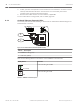
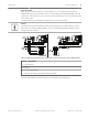


Table Of Contents
- Title Page
- Table of Contents
- Certifications, approvals, listings, and safety
- Introduction
- System overview
- Installation checklist
- Control panel installation
- Power supply
- Telephone communications
- IP communications
- Keypads, keyswitches, keyfobs and transmitters
- Keypads
- B915 Basic Keypad
- B920 Two-line Alphanumeric Keypad
- B921C Two-line Capacitive Keypad with Inputs
- B930 ATM Style Alphanumeric Keypad
- B942 Touch Screen Keypad
- Shortcuts and custom functions
- Address settings
- Supervision
- Installation and control panel wiring (keypads)
- Sensor loops overview and wiring (B921C/B942/B942W only)
- Output wiring (B942/B942W only)
- Troubleshooting
- Keyswitches
- RADION keyfobs and Inovonics pendant transmitters
- Keypads
- On-board outputs
- Off-board outputs
- On-board points
- Off-board points
- Wireless modules
- Access control
- Program and test the control panel
- Control panel board overview
- System wiring diagrams
- Approved applications
- Keypad Installer menu
- [1] Program menu
- [1] Reporting > [1] Phone menu parameters
- [1] Reporting > [2] Network menu parameters
- [1] Reporting > [3] Routing menu parameters
- [1] Reporting > [4] Personal Note menu parameters
- [2] Network > [1] Ethernet > (choose the bus module or on-board) > [1] Module Parameters menu
- [2] Network > [1] Ethernet > (choose the bus module or on-board) > [2] Address Parameters menu
- [2] Network > [1] Ethernet > (choose the bus module or on-board) > [3] DNS Parameters menu
- [2] Network > [2] Cellular > (choose the SDI2 cellular module or plug-in module)
- [3] RPS > [1] RPS Passcode menu parameters
- [3] RPS > [2] RPS Phone Number menu parameters
- [3] RPS > [3] RPS IP Address menu parameters
- [3] RPS > [4] RPS Port Number menu parameters
- [4] Area Options menu parameters
- [5] Keypad menu parameters
- [6] Users menu parameters
- [7] Points menu parameters
- [8] Disable Programming menu
- [2] Wireless menu
- [1] RF Point Menu> [1] Enroll Point RFID
- [1] RF Point Menu> [2] Replace Point RFID
- [1] RF Point Menu> [3] Remove Point RFID
- [2] RF Repeater Menu > [1] Add Repeater
- [2] RF Repeater Menu > [2] Replace Repeater
- [2] RF Repeater Menu > [3] Remove Repeater
- [3] RF Diagnostic Menu > [1] RF Points
- [3] RF Diagnostic Menu > [2] RF Repeater Menu
- [3] Diags menu
- [4] Serv Byp (Service Bypass) menu
- [5] Versions menu
- [6] Cloud menu
- [1] Program menu
- Specifications
- Appendix
- Back Page

IP communications
IP communication
The control panel can use on-board Ethernet (IP) connection (the on-board Ethernet port is
excluded on “E” versions) to communicate with a Conettix D6600 or a Conettix D6100IPv6
Communications Receiver/Gateway.
The control panel can optionally use a B426 Conettix Ethernet Communication Module or a
Conettix Plug-in Cellular Communicator (B440/B441/B442/B443).
Using Conettix IP communication offers a secure path that includes anti-replay/anti-
substitution features and provides enhanced security with AES 256-bit encryption (using
Cipher Block Chaining (CBC)).
The control panel supports Domain Name System (DNS) for both remote programming and
central station communication. DNS provides ease of use, eliminating the need to use static IP
addresses as your reporting destination, and accommodates a simple solution for central
station disaster recovery. IP Setup is easy, eliminating the need to use complicated internet
programming tools such as ARP and Telnet. The control panel supports both IPv6 and IPv4
networks.
Notice!
For premises equipment used in the communication path, such as routers, use only UL listed
equipment.
On-board Ethernet connection
The built-in Ethernet port on the control panels allows for a network connection without the
need for additional modules. The port supports both 10 Base-T (10 Mb) and 100 Base-TX (100
Mb) standards. The port supports full duplex, half duplex, and HP AUTO_MDIX communication,
using a standard Ethernet cable. Optionally use this connection for central station reporting,
automation, and programming.
Supervision
The control panel supervises its on-board Ethernet connection when the control panel uses
the on-board Ethernet in any of the four route groups as part of either the primary route or the
backup route, or when the control panel uses the connection as the automation device.
Supervision ensures reliable operation of the Ethernet port.
If supervised and the on-board Ethernet does not respond to control panel supervision polls,
then a system fault message appears at the keypads.
Local RPS programming
Use the on-board Ethernet connection to locally connect with RPS. This connection method
requires a direct IP connection from the RPS computer to the on-board Ethernet port.
Connecting the control panel to RPS using IP Direct:
1. If the control panel does not use the Ethernet for IP communication, perform Steps 2 and
3. If the control panel does use the Ethernet for IP communication, power down the
control panel and remove the Ethernet cable that connects the control panel to the
network.
2. Connect the control panel to the RPS computer using the Ethernet ports and a standard
Ethernet cable, and apply power to the control panel, if applicable. Within 2 minutes, the
RPS computer assigns an IP address using AutoIP.
8
8.1
8.1.1
8.1.2
Control Panel IP communications | en 41
Bosch Security Systems, Inc. Installation and System Reference Guide 2016.05 | 14 | F.01U.287.180