
Installation Manual
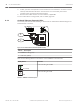
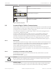
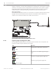
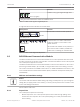
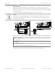


Table Of Contents
- Title Page
- Table of Contents
- Certifications, approvals, listings, and safety
- Introduction
- System overview
- Installation checklist
- Control panel installation
- Power supply
- Telephone communications
- IP communications
- Keypads, keyswitches, keyfobs and transmitters
- Keypads
- B915 Basic Keypad
- B920 Two-line Alphanumeric Keypad
- B921C Two-line Capacitive Keypad with Inputs
- B930 ATM Style Alphanumeric Keypad
- B942 Touch Screen Keypad
- Shortcuts and custom functions
- Address settings
- Supervision
- Installation and control panel wiring (keypads)
- Sensor loops overview and wiring (B921C/B942/B942W only)
- Output wiring (B942/B942W only)
- Troubleshooting
- Keyswitches
- RADION keyfobs and Inovonics pendant transmitters
- Keypads
- On-board outputs
- Off-board outputs
- On-board points
- Off-board points
- Wireless modules
- Access control
- Program and test the control panel
- Control panel board overview
- System wiring diagrams
- Approved applications
- Keypad Installer menu
- [1] Program menu
- [1] Reporting > [1] Phone menu parameters
- [1] Reporting > [2] Network menu parameters
- [1] Reporting > [3] Routing menu parameters
- [1] Reporting > [4] Personal Note menu parameters
- [2] Network > [1] Ethernet > (choose the bus module or on-board) > [1] Module Parameters menu
- [2] Network > [1] Ethernet > (choose the bus module or on-board) > [2] Address Parameters menu
- [2] Network > [1] Ethernet > (choose the bus module or on-board) > [3] DNS Parameters menu
- [2] Network > [2] Cellular > (choose the SDI2 cellular module or plug-in module)
- [3] RPS > [1] RPS Passcode menu parameters
- [3] RPS > [2] RPS Phone Number menu parameters
- [3] RPS > [3] RPS IP Address menu parameters
- [3] RPS > [4] RPS Port Number menu parameters
- [4] Area Options menu parameters
- [5] Keypad menu parameters
- [6] Users menu parameters
- [7] Points menu parameters
- [8] Disable Programming menu
- [2] Wireless menu
- [1] RF Point Menu> [1] Enroll Point RFID
- [1] RF Point Menu> [2] Replace Point RFID
- [1] RF Point Menu> [3] Remove Point RFID
- [2] RF Repeater Menu > [1] Add Repeater
- [2] RF Repeater Menu > [2] Replace Repeater
- [2] RF Repeater Menu > [3] Remove Repeater
- [3] RF Diagnostic Menu > [1] RF Points
- [3] RF Diagnostic Menu > [2] RF Repeater Menu
- [3] Diags menu
- [4] Serv Byp (Service Bypass) menu
- [5] Versions menu
- [6] Cloud menu
- [1] Program menu
- Specifications
- Appendix
- Back Page

Flash pattern Function
On Steady
Plugged into an Ethernet network.
Flashing
Communication in progress.
Off
Unplugged from an Ethernet network, or the Ethernet
network is not available.
Table 8.2: LINK LED descriptions
Conettix Plug-in Cellular Communicators
Cellular plug-in communicators provide communication between the control panel and central
monitoring stations or RPS using a cellular network. The module also sends and receives SMS
messages for personal notification or system configuration.
The control panel supports one Connetix plug-in cellular module (directly plugged into the
control panel or plugged into a B450).
Connect a module using the plug-in module connector or using a B450 Conettix Plug-in
Communicator Interface (refer to the Conettix Plug-in Communicator Interface (B450)
Installation and Operation Guide and B450 Conettix Plug-in Communicator Interface, page 49).
This section includes basic installation instructions. For detailed instructions, refer to the
corresponding Conettix plug-in module document listed in Related documentation, page 11.
Supervision
The control panel supervises a plug-in cellular communicator when the control panel uses the
module in any of the four route groups as part of either the primary route or the backup route,
and the control panel uses the module to route any personal notifications. Supervision
ensures reliable operation between the module and the control panel.
If supervised and the module does not respond to control panel supervision polls, then a
system fault message shows on the keypads. The control panel sends a corresponding report
to the central station.
Installation and module wiring (B44x)
Ensure that there is enough power for the module and other powered devices you want
connected to the system.
Refer to On-board outputs, page 60.
!
Caution!
Remove all power (AC and battery) before making any connections. Failure to do so might
result in personal injury and/or equipment damage.
Install the module
The module plugs into a connector and is held in place with a plug-in module retention clip.
The module handle and support on top of the module hold the unit during installation.
8.2
8.2.1
8.2.2
Control Panel IP communications | en 43
Bosch Security Systems, Inc. Installation and System Reference Guide 2016.05 | 14 | F.01U.287.180