
Installation Manual
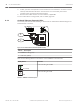
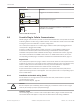
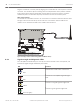
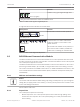
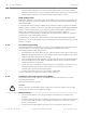
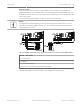


Table Of Contents
- Title Page
- Table of Contents
- Certifications, approvals, listings, and safety
- Introduction
- System overview
- Installation checklist
- Control panel installation
- Power supply
- Telephone communications
- IP communications
- Keypads, keyswitches, keyfobs and transmitters
- Keypads
- B915 Basic Keypad
- B920 Two-line Alphanumeric Keypad
- B921C Two-line Capacitive Keypad with Inputs
- B930 ATM Style Alphanumeric Keypad
- B942 Touch Screen Keypad
- Shortcuts and custom functions
- Address settings
- Supervision
- Installation and control panel wiring (keypads)
- Sensor loops overview and wiring (B921C/B942/B942W only)
- Output wiring (B942/B942W only)
- Troubleshooting
- Keyswitches
- RADION keyfobs and Inovonics pendant transmitters
- Keypads
- On-board outputs
- Off-board outputs
- On-board points
- Off-board points
- Wireless modules
- Access control
- Program and test the control panel
- Control panel board overview
- System wiring diagrams
- Approved applications
- Keypad Installer menu
- [1] Program menu
- [1] Reporting > [1] Phone menu parameters
- [1] Reporting > [2] Network menu parameters
- [1] Reporting > [3] Routing menu parameters
- [1] Reporting > [4] Personal Note menu parameters
- [2] Network > [1] Ethernet > (choose the bus module or on-board) > [1] Module Parameters menu
- [2] Network > [1] Ethernet > (choose the bus module or on-board) > [2] Address Parameters menu
- [2] Network > [1] Ethernet > (choose the bus module or on-board) > [3] DNS Parameters menu
- [2] Network > [2] Cellular > (choose the SDI2 cellular module or plug-in module)
- [3] RPS > [1] RPS Passcode menu parameters
- [3] RPS > [2] RPS Phone Number menu parameters
- [3] RPS > [3] RPS IP Address menu parameters
- [3] RPS > [4] RPS Port Number menu parameters
- [4] Area Options menu parameters
- [5] Keypad menu parameters
- [6] Users menu parameters
- [7] Points menu parameters
- [8] Disable Programming menu
- [2] Wireless menu
- [1] RF Point Menu> [1] Enroll Point RFID
- [1] RF Point Menu> [2] Replace Point RFID
- [1] RF Point Menu> [3] Remove Point RFID
- [2] RF Repeater Menu > [1] Add Repeater
- [2] RF Repeater Menu > [2] Replace Repeater
- [2] RF Repeater Menu > [3] Remove Repeater
- [3] RF Diagnostic Menu > [1] RF Points
- [3] RF Diagnostic Menu > [2] RF Repeater Menu
- [3] Diags menu
- [4] Serv Byp (Service Bypass) menu
- [5] Versions menu
- [6] Cloud menu
- [1] Program menu
- Specifications
- Appendix
- Back Page

Flash pattern Function
RX (Receive) Flashing
Occurs when the module receives a message over the
network connection – UPD, TCP, or DNS.
TX (Transmit) Flashing
Occurs when the module sends a message over the
network connection – UPD, TCP, or DNS.
Table 8.6: RX and TX LEDs descriptions
LINK (yellow) LED pattern
100Mb (green) LED pattern Function
Off Off
No Ethernet link
On Steady
Off
10Base-T link
Flashing
Off
10Base-T activity
On Steady On Steady
100Base-TX link
Flashing
On Steady
100Base-TX activity
Table 8.7: Ethernet Link LEDs descriptions
B450 Conettix Plug-in Communicator Interface
The B450 Conettix Plug-in Communicator Interface gives the ability to connect more than one
cellular plug-in communicator to the control panel by providing an interface to the control
panel’s SDI2 wiring.
The B450 supports one cellular plug-in module.
The B450 Conettix Plug-in Communicator Interface connects to the SDI2 bus on the control
panel using terminals PWR, A, B, and COM, or using the SDI2 interconnect wiring connector.
This section includes basic installation instructions. For detailed installation instructions, refer
to the Conettix Plug-in Communicator Interface (B450) Installation and Operation Guide.
8.4
Control Panel IP communications | en 49
Bosch Security Systems, Inc. Installation and System Reference Guide 2016.05 | 14 | F.01U.287.180