
Installation Manual
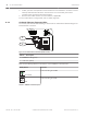
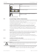
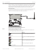
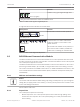
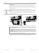


Table Of Contents
- Title Page
- Table of Contents
- Certifications, approvals, listings, and safety
- Introduction
- System overview
- Installation checklist
- Control panel installation
- Power supply
- Telephone communications
- IP communications
- Keypads, keyswitches, keyfobs and transmitters
- Keypads
- B915 Basic Keypad
- B920 Two-line Alphanumeric Keypad
- B921C Two-line Capacitive Keypad with Inputs
- B930 ATM Style Alphanumeric Keypad
- B942 Touch Screen Keypad
- Shortcuts and custom functions
- Address settings
- Supervision
- Installation and control panel wiring (keypads)
- Sensor loops overview and wiring (B921C/B942/B942W only)
- Output wiring (B942/B942W only)
- Troubleshooting
- Keyswitches
- RADION keyfobs and Inovonics pendant transmitters
- Keypads
- On-board outputs
- Off-board outputs
- On-board points
- Off-board points
- Wireless modules
- Access control
- Program and test the control panel
- Control panel board overview
- System wiring diagrams
- Approved applications
- Keypad Installer menu
- [1] Program menu
- [1] Reporting > [1] Phone menu parameters
- [1] Reporting > [2] Network menu parameters
- [1] Reporting > [3] Routing menu parameters
- [1] Reporting > [4] Personal Note menu parameters
- [2] Network > [1] Ethernet > (choose the bus module or on-board) > [1] Module Parameters menu
- [2] Network > [1] Ethernet > (choose the bus module or on-board) > [2] Address Parameters menu
- [2] Network > [1] Ethernet > (choose the bus module or on-board) > [3] DNS Parameters menu
- [2] Network > [2] Cellular > (choose the SDI2 cellular module or plug-in module)
- [3] RPS > [1] RPS Passcode menu parameters
- [3] RPS > [2] RPS Phone Number menu parameters
- [3] RPS > [3] RPS IP Address menu parameters
- [3] RPS > [4] RPS Port Number menu parameters
- [4] Area Options menu parameters
- [5] Keypad menu parameters
- [6] Users menu parameters
- [7] Points menu parameters
- [8] Disable Programming menu
- [2] Wireless menu
- [1] RF Point Menu> [1] Enroll Point RFID
- [1] RF Point Menu> [2] Replace Point RFID
- [1] RF Point Menu> [3] Remove Point RFID
- [2] RF Repeater Menu > [1] Add Repeater
- [2] RF Repeater Menu > [2] Replace Repeater
- [2] RF Repeater Menu > [3] Remove Repeater
- [3] RF Diagnostic Menu > [1] RF Points
- [3] RF Diagnostic Menu > [2] RF Repeater Menu
- [3] Diags menu
- [4] Serv Byp (Service Bypass) menu
- [5] Versions menu
- [6] Cloud menu
- [1] Program menu
- Specifications
- Appendix
- Back Page

SDI2 address settings
Notice!
The module reads the address switch setting only during module power up. If you change the
setting after you apply power to the module, you must cycle the power to the module in order
for the new setting to take effect.
The control panel supports one module. Set the address switch to 1 to use the module with
the control panel.
Supervision
The control panel supervises in two ways:
– Module supervision. The control panel supervises the module through polling. If the
module does not respond to the control panel polling, the control panel declares the
device missing.
– Communication supervision. The control panel supervises the communication path by
polling the central station receiver. If the poll is missed from either side, a communication
fault is declared both at the control panel and the central station receiver.
Installation and control panel wiring (B450)
Ensure that there is enough power for the module and other powered devices you want
connected to the system.
Refer to On-board outputs, page 60.
!
Caution!
Remove all power (AC and battery) before making any connections. Failure to do so might
result in personal injury and/or equipment damage.
Insert the communication module
Insert the desired communication module into the slot of the B450 until you hear the module
“click” into place.
Install the module
1. Set the module address to one using the address switch before you install it in the
enclosure.
2. Install the module in the enclosure with the control panel or in an adjacent enclosure that
is no more than 1000 ft (305 m) using 18 AWG to 22 AWG (1.02 mm to 0.65 mm) wire
from the control panel.
3. Use the screws provided with the module to secure the module in the enclosure.
Wire to the antenna
The module has a threaded connector for connection to an antenna. Route the antenna cable
through a wire knockout in the top of the enclosure. Connect the antenna cable to the
module. Secure the antenna cable to the outside of the enclosure.
When you wire an SDI2 module to a control panel, you can use either the terminal strip
labeled with PWR, A, B, and COM to wire to corresponding terminals labeled PWR, A, B, and
COM on the control panel, or you can use the interconnect wiring connector and the included
interconnect cable.
For terminal wiring, use 18 AWG to 22 AWG (1.02 mm to 0.65 mm) wire.
8.4.1
8.4.2
8.4.3
50 en | IP communications Control Panel
2016.05 | 14 | F.01U.287.180 Installation and System Reference Guide Bosch Security Systems, Inc.