
Installation Manual

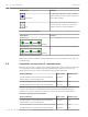
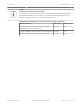
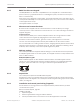
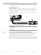
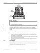
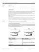
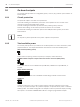
Table Of Contents
- Title Page
- Table of Contents
- Certifications, approvals, listings, and safety
- Introduction
- System overview
- Installation checklist
- Control panel installation
- Power supply
- Telephone communications
- IP communications
- Keypads, keyswitches, keyfobs and transmitters
- Keypads
- B915 Basic Keypad
- B920 Two-line Alphanumeric Keypad
- B921C Two-line Capacitive Keypad with Inputs
- B930 ATM Style Alphanumeric Keypad
- B942 Touch Screen Keypad
- Shortcuts and custom functions
- Address settings
- Supervision
- Installation and control panel wiring (keypads)
- Sensor loops overview and wiring (B921C/B942/B942W only)
- Output wiring (B942/B942W only)
- Troubleshooting
- Keyswitches
- RADION keyfobs and Inovonics pendant transmitters
- Keypads
- On-board outputs
- Off-board outputs
- On-board points
- Off-board points
- Wireless modules
- Access control
- Program and test the control panel
- Control panel board overview
- System wiring diagrams
- Approved applications
- Keypad Installer menu
- [1] Program menu
- [1] Reporting > [1] Phone menu parameters
- [1] Reporting > [2] Network menu parameters
- [1] Reporting > [3] Routing menu parameters
- [1] Reporting > [4] Personal Note menu parameters
- [2] Network > [1] Ethernet > (choose the bus module or on-board) > [1] Module Parameters menu
- [2] Network > [1] Ethernet > (choose the bus module or on-board) > [2] Address Parameters menu
- [2] Network > [1] Ethernet > (choose the bus module or on-board) > [3] DNS Parameters menu
- [2] Network > [2] Cellular > (choose the SDI2 cellular module or plug-in module)
- [3] RPS > [1] RPS Passcode menu parameters
- [3] RPS > [2] RPS Phone Number menu parameters
- [3] RPS > [3] RPS IP Address menu parameters
- [3] RPS > [4] RPS Port Number menu parameters
- [4] Area Options menu parameters
- [5] Keypad menu parameters
- [6] Users menu parameters
- [7] Points menu parameters
- [8] Disable Programming menu
- [2] Wireless menu
- [1] RF Point Menu> [1] Enroll Point RFID
- [1] RF Point Menu> [2] Replace Point RFID
- [1] RF Point Menu> [3] Remove Point RFID
- [2] RF Repeater Menu > [1] Add Repeater
- [2] RF Repeater Menu > [2] Replace Repeater
- [2] RF Repeater Menu > [3] Remove Repeater
- [3] RF Diagnostic Menu > [1] RF Points
- [3] RF Diagnostic Menu > [2] RF Repeater Menu
- [3] Diags menu
- [4] Serv Byp (Service Bypass) menu
- [5] Versions menu
- [6] Cloud menu
- [1] Program menu
- Specifications
- Appendix
- Back Page

Notice!
Use either the terminal strip wiring or interconnect wiring to the control panel. Do not use
both. When connecting multiple modules, you can combine terminal strip and interconnect
wiring connectors in series.
R
Y
G
B
R
Y
G
B
3.7 - 5.0 VDC
2.0 - 3.0 VDC
0.0 - 1.3 VDC
Open
Normal
Short
3
R
Y
G
B
1
1
2
4
2
7 COM 8
C
OUTPUT
B
1 k End of Line Resistors
Voltage Ranges
ON-BOARD POINTS
3 COM 4 5 COM 61 COM 2
R Y G B
SDI2
Device Bus
AUX
- 12 V +
7 COM 8
C
OUTPUT
B
1 k End of Line Resistors
Voltage Ranges
ON-BOARD POINTS
3.7 - 5.0 VDC
2.0 - 3.0 VDC
0.0 - 1.3 VDC
Open
Normal
Short
3 COM 4 5 COM 61 COM 2
R Y G B
SDI2
Device Bus
AUX
- 12 V +
TMPR
1 COM 2 7 COM 83 COM 4 5 COM 6
RESET
COM AUX R Y G B
PWR A B COM
B C
OUTPUT
TMPR
1 COM 2 7 COM 83 COM 4 5 COM 6
RESET
COM AUX R Y G B
PWR A B COM
B C
OUTPUT
Figure 8.5: B450 to control panel wiring - terminal strip or interconnect wiring connector (B5512 shown)
Callout ᅳ Description
1 ᅳ Control panel
2 ᅳ Module
3 ᅳTerminal strip wiring
4 ᅳ Interconnect cable
Diagnostic LEDs
The B450 includes the following on-board LEDs to assist with troubleshooting:
– Heartbeat (system status).
– RX (receive).
– TX (transmit).
The plug-in module also includes LEDs for troubleshooting and status.
Flash pattern Function
Flashes
once every 1 sec
Normal state. Indicates normal operation.
3 quick flashes every 1 sec
Communication error state. Indicates a bus
communication error with the control panel.
8.4.4
Control Panel IP communications | en 51
Bosch Security Systems, Inc. Installation and System Reference Guide 2016.05 | 14 | F.01U.287.180