
Installation Manual

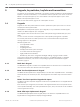
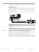
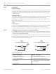
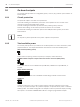
Table Of Contents
- Title Page
- Table of Contents
- Certifications, approvals, listings, and safety
- Introduction
- System overview
- Installation checklist
- Control panel installation
- Power supply
- Telephone communications
- IP communications
- Keypads, keyswitches, keyfobs and transmitters
- Keypads
- B915 Basic Keypad
- B920 Two-line Alphanumeric Keypad
- B921C Two-line Capacitive Keypad with Inputs
- B930 ATM Style Alphanumeric Keypad
- B942 Touch Screen Keypad
- Shortcuts and custom functions
- Address settings
- Supervision
- Installation and control panel wiring (keypads)
- Sensor loops overview and wiring (B921C/B942/B942W only)
- Output wiring (B942/B942W only)
- Troubleshooting
- Keyswitches
- RADION keyfobs and Inovonics pendant transmitters
- Keypads
- On-board outputs
- Off-board outputs
- On-board points
- Off-board points
- Wireless modules
- Access control
- Program and test the control panel
- Control panel board overview
- System wiring diagrams
- Approved applications
- Keypad Installer menu
- [1] Program menu
- [1] Reporting > [1] Phone menu parameters
- [1] Reporting > [2] Network menu parameters
- [1] Reporting > [3] Routing menu parameters
- [1] Reporting > [4] Personal Note menu parameters
- [2] Network > [1] Ethernet > (choose the bus module or on-board) > [1] Module Parameters menu
- [2] Network > [1] Ethernet > (choose the bus module or on-board) > [2] Address Parameters menu
- [2] Network > [1] Ethernet > (choose the bus module or on-board) > [3] DNS Parameters menu
- [2] Network > [2] Cellular > (choose the SDI2 cellular module or plug-in module)
- [3] RPS > [1] RPS Passcode menu parameters
- [3] RPS > [2] RPS Phone Number menu parameters
- [3] RPS > [3] RPS IP Address menu parameters
- [3] RPS > [4] RPS Port Number menu parameters
- [4] Area Options menu parameters
- [5] Keypad menu parameters
- [6] Users menu parameters
- [7] Points menu parameters
- [8] Disable Programming menu
- [2] Wireless menu
- [1] RF Point Menu> [1] Enroll Point RFID
- [1] RF Point Menu> [2] Replace Point RFID
- [1] RF Point Menu> [3] Remove Point RFID
- [2] RF Repeater Menu > [1] Add Repeater
- [2] RF Repeater Menu > [2] Replace Repeater
- [2] RF Repeater Menu > [3] Remove Repeater
- [3] RF Diagnostic Menu > [1] RF Points
- [3] RF Diagnostic Menu > [2] RF Repeater Menu
- [3] Diags menu
- [4] Serv Byp (Service Bypass) menu
- [5] Versions menu
- [6] Cloud menu
- [1] Program menu
- Specifications
- Appendix
- Back Page

Operation
Maintained contact
For points connected to the keyswitch and programmed for a maintained contact, an open on
the sensor loop turns the area All On (armed). The control panel force arms all faulted points,
regardless of the entry in the FA Bypass Max program item. Returning the circuit to normal
turns the area off.
Momentary contact
For points connected to the keyswitch and programmed for a momentary contact, shorting the
arming sensor loop toggles the area's arming state between All On (armed) and Off
(disarmed). The control panel force arms all faulted points, regardless of the entry in the FA
Bypass Max program item.
Refer to Area Parameters and Point Assignments in RPS Help or the control panel Program Entry
Guide.
Silence the bell
To silence the bell (stop Alarm Bell output) if the system is On (armed), operate the keyswitch
to turn the area off. If the area is disarmed, turn the keyswitch once to start the arming
process. Turning the keyswitch a second time stops the arming process and silences the bell.
Installation and control panel wiring (keyswitches)
For maintained switches, connect the EOL resistor for the point at the keyswitch so that the
switch opens the circuit when it operates. A short on the circuit produces an alarm if the area
is armed and a trouble if it is disarmed.
For momentary keyswitches, connect the EOL resistor at the keyswitch point so that when the
keyswitch operates, it shorts the resistor. An open on the circuit causes an alarm if the area is
on (armed) and a trouble if it is off (disarmed).
2
3
4
5
3
4
5
6
7
1
Figure 9.3: Keyswitch wiring
Callout ᅳ Description
Callout ᅳ Description
1 ᅳ Maintained keyswitch 5 ᅳ EOL (End of Line) resistor
2 ᅳ Momentary keyswitch 6 ᅳ Open on the circuit arms the area
3 ᅳ Common 7 ᅳ Momentary short on the circuit toggles
the arming state
4 ᅳ Point input
Keyswitches are not intended for use in UL listed systems.
9.2.1
9.2.2
58 en | Keypads, keyswitches, keyfobs and transmitters Control Panel
2016.05 | 14 | F.01U.287.180 Installation and System Reference Guide Bosch Security Systems, Inc.