
Installation Manual

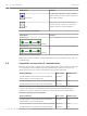
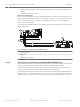
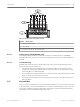
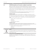
Table Of Contents
- Title Page
- Table of Contents
- Certifications, approvals, listings, and safety
- Introduction
- System overview
- Installation checklist
- Control panel installation
- Power supply
- Telephone communications
- IP communications
- Keypads, keyswitches, keyfobs and transmitters
- Keypads
- B915 Basic Keypad
- B920 Two-line Alphanumeric Keypad
- B921C Two-line Capacitive Keypad with Inputs
- B930 ATM Style Alphanumeric Keypad
- B942 Touch Screen Keypad
- Shortcuts and custom functions
- Address settings
- Supervision
- Installation and control panel wiring (keypads)
- Sensor loops overview and wiring (B921C/B942/B942W only)
- Output wiring (B942/B942W only)
- Troubleshooting
- Keyswitches
- RADION keyfobs and Inovonics pendant transmitters
- Keypads
- On-board outputs
- Off-board outputs
- On-board points
- Off-board points
- Wireless modules
- Access control
- Program and test the control panel
- Control panel board overview
- System wiring diagrams
- Approved applications
- Keypad Installer menu
- [1] Program menu
- [1] Reporting > [1] Phone menu parameters
- [1] Reporting > [2] Network menu parameters
- [1] Reporting > [3] Routing menu parameters
- [1] Reporting > [4] Personal Note menu parameters
- [2] Network > [1] Ethernet > (choose the bus module or on-board) > [1] Module Parameters menu
- [2] Network > [1] Ethernet > (choose the bus module or on-board) > [2] Address Parameters menu
- [2] Network > [1] Ethernet > (choose the bus module or on-board) > [3] DNS Parameters menu
- [2] Network > [2] Cellular > (choose the SDI2 cellular module or plug-in module)
- [3] RPS > [1] RPS Passcode menu parameters
- [3] RPS > [2] RPS Phone Number menu parameters
- [3] RPS > [3] RPS IP Address menu parameters
- [3] RPS > [4] RPS Port Number menu parameters
- [4] Area Options menu parameters
- [5] Keypad menu parameters
- [6] Users menu parameters
- [7] Points menu parameters
- [8] Disable Programming menu
- [2] Wireless menu
- [1] RF Point Menu> [1] Enroll Point RFID
- [1] RF Point Menu> [2] Replace Point RFID
- [1] RF Point Menu> [3] Remove Point RFID
- [2] RF Repeater Menu > [1] Add Repeater
- [2] RF Repeater Menu > [2] Replace Repeater
- [2] RF Repeater Menu > [3] Remove Repeater
- [3] RF Diagnostic Menu > [1] RF Points
- [3] RF Diagnostic Menu > [2] RF Repeater Menu
- [3] Diags menu
- [4] Serv Byp (Service Bypass) menu
- [5] Versions menu
- [6] Cloud menu
- [1] Program menu
- Specifications
- Appendix
- Back Page

On-board outputs
The control panel provides one configurable (power, common, dry) and two open collector on-
board outputs.
Circuit protection
The powered outputs come with circuit protection.
Three self-resetting circuit breakers protect the control panel from short circuits on the
continuous and programmable power outputs.
One self-resetting circuit breaker protects the AUX (auxiliary power) terminal.
Another self-resetting circuit breaker protects the OUTPUT A’s C terminal.
The third self-resetting circuit breaker protects the PWR/R terminal (power) of the SDI2
terminal block.
Notice!
UL requires any device powered from a power output to be supervised.
Total available power
The control panel produces up to 800 mA of combined power at 12.0 VDC nominal to power
peripheral devices. The outputs listed below and OUTPUT A share the available power.
AUX terminal (auxiliary power)
AUX
Powers devices requiring continuous power (for example, motion detectors).
R/PWR terminal and power output of the interconnect connector (SDI2 power)
R
PWR
Power SDI2 devices such as a B208 Octo-input Module, a B308 Octo-output Module, or
keypads.
Plug-in module connector
Connect plug-in modules such as the B440 Conettix Plug-in Cellular Communicator.
OUTPUT A
NO C NC
OUTPUT A
Configure Output A as a dry contact (contact rating is 3 Amps), switched common (sink
current), or a powered output. As a powered output, it can provide alarm power or switched
auxiliary power. The default configuration for Output A makes it a powered output providing
alarm power. Use OUTPUT PARAMETERS in RPS to configure programmable outputs.
10
10.1
10.2
60 en | On-board outputs Control Panel
2016.05 | 14 | F.01U.287.180 Installation and System Reference Guide Bosch Security Systems, Inc.