
Installation Manual
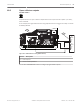


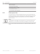


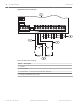
Table Of Contents
- Title Page
- Table of Contents
- Certifications, approvals, listings, and safety
- Introduction
- System overview
- Installation checklist
- Control panel installation
- Power supply
- Telephone communications
- IP communications
- Keypads, keyswitches, keyfobs and transmitters
- Keypads
- B915 Basic Keypad
- B920 Two-line Alphanumeric Keypad
- B921C Two-line Capacitive Keypad with Inputs
- B930 ATM Style Alphanumeric Keypad
- B942 Touch Screen Keypad
- Shortcuts and custom functions
- Address settings
- Supervision
- Installation and control panel wiring (keypads)
- Sensor loops overview and wiring (B921C/B942/B942W only)
- Output wiring (B942/B942W only)
- Troubleshooting
- Keyswitches
- RADION keyfobs and Inovonics pendant transmitters
- Keypads
- On-board outputs
- Off-board outputs
- On-board points
- Off-board points
- Wireless modules
- Access control
- Program and test the control panel
- Control panel board overview
- System wiring diagrams
- Approved applications
- Keypad Installer menu
- [1] Program menu
- [1] Reporting > [1] Phone menu parameters
- [1] Reporting > [2] Network menu parameters
- [1] Reporting > [3] Routing menu parameters
- [1] Reporting > [4] Personal Note menu parameters
- [2] Network > [1] Ethernet > (choose the bus module or on-board) > [1] Module Parameters menu
- [2] Network > [1] Ethernet > (choose the bus module or on-board) > [2] Address Parameters menu
- [2] Network > [1] Ethernet > (choose the bus module or on-board) > [3] DNS Parameters menu
- [2] Network > [2] Cellular > (choose the SDI2 cellular module or plug-in module)
- [3] RPS > [1] RPS Passcode menu parameters
- [3] RPS > [2] RPS Phone Number menu parameters
- [3] RPS > [3] RPS IP Address menu parameters
- [3] RPS > [4] RPS Port Number menu parameters
- [4] Area Options menu parameters
- [5] Keypad menu parameters
- [6] Users menu parameters
- [7] Points menu parameters
- [8] Disable Programming menu
- [2] Wireless menu
- [1] RF Point Menu> [1] Enroll Point RFID
- [1] RF Point Menu> [2] Replace Point RFID
- [1] RF Point Menu> [3] Remove Point RFID
- [2] RF Repeater Menu > [1] Add Repeater
- [2] RF Repeater Menu > [2] Replace Repeater
- [2] RF Repeater Menu > [3] Remove Repeater
- [3] RF Diagnostic Menu > [1] RF Points
- [3] RF Diagnostic Menu > [2] RF Repeater Menu
- [3] Diags menu
- [4] Serv Byp (Service Bypass) menu
- [5] Versions menu
- [6] Cloud menu
- [1] Program menu
- Specifications
- Appendix
- Back Page

Off-board outputs
The control panel supports off-board outputs using the B308 Octo-output Module.
B308 Octo-output Module
The B308 is an eight output expansion device that connects to control panels through the
SDI2 bus. This module is supervised for the connection to the SDI2 bus. It provides eight
independently controlled outputs. Each output can operate as either normally open or
normally closed. You can configure the function for each output on the module individually.
Refer to Output Parameters in RPS Help or the control panel Program Entry Guide.
B6512 control panels support up to 9 modules to provide 72 outputs.
B5512 control panels support up to 5 modules to provide 40 outputs. B4512 control panels
support up to 3 modules to provide 24 outputs.
The B3512 does not support the B308 module.
B308 Octo-output Modules connect to the SDI2 bus on the control panel using terminals PWR,
A, B, and COM, or using the SDI2 interconnect wiring connector. You can connect more than
one module to the control panel by wiring them in parallel. This section includes basic
installation instructions. For detailed installation instructions, refer to the Octo-output Module
(B308) Installation and Operation Guide.
Notice!
Do not connect fire and non-fire devices to the same B308 Octo-output Module.
Outputs overview
Each module output provides a Form C dry contact rated for .001 to 1.0 A at 5 to 24 VDC
(resistive load). Normally-open, common, and normally-closed terminals are available for each
relay output. When an individual output is activated, continuity exists between the normally
open and common terminals. When the output is not activated, continuity exists between the
normally closed and common terminals.
SDI2 address settings
Notice!
The module reads the address switch setting only during module power up. If you change the
setting after you apply power to the module, you must cycle the power to the module in order
for the new setting to take effect.
If multiple B308 modules reside on the same system, each B308 module must have a unique
address.
The number of outputs allowed by the control panel determines the valid addresses.
For valid output numbers, refer to B308 address settings, page 150.
Supervision
The control panel enables supervision of B308 Octo-output Modules on the SDI2 bus when the
Output Source of an off-board output is set to Octo-output.
With any failure to receive an expected response from the module, all keypads show a system
fault. The control panel sends a module trouble report to the central station (if configured for
module trouble reports).
11
11.1
11.1.1
11.1.2
62 en | Off-board outputs Control Panel
2016.05 | 14 | F.01U.287.180 Installation and System Reference Guide Bosch Security Systems, Inc.