
Installation Manual
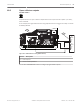


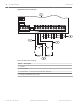
Table Of Contents
- Title Page
- Table of Contents
- Certifications, approvals, listings, and safety
- Introduction
- System overview
- Installation checklist
- Control panel installation
- Power supply
- Telephone communications
- IP communications
- Keypads, keyswitches, keyfobs and transmitters
- Keypads
- B915 Basic Keypad
- B920 Two-line Alphanumeric Keypad
- B921C Two-line Capacitive Keypad with Inputs
- B930 ATM Style Alphanumeric Keypad
- B942 Touch Screen Keypad
- Shortcuts and custom functions
- Address settings
- Supervision
- Installation and control panel wiring (keypads)
- Sensor loops overview and wiring (B921C/B942/B942W only)
- Output wiring (B942/B942W only)
- Troubleshooting
- Keyswitches
- RADION keyfobs and Inovonics pendant transmitters
- Keypads
- On-board outputs
- Off-board outputs
- On-board points
- Off-board points
- Wireless modules
- Access control
- Program and test the control panel
- Control panel board overview
- System wiring diagrams
- Approved applications
- Keypad Installer menu
- [1] Program menu
- [1] Reporting > [1] Phone menu parameters
- [1] Reporting > [2] Network menu parameters
- [1] Reporting > [3] Routing menu parameters
- [1] Reporting > [4] Personal Note menu parameters
- [2] Network > [1] Ethernet > (choose the bus module or on-board) > [1] Module Parameters menu
- [2] Network > [1] Ethernet > (choose the bus module or on-board) > [2] Address Parameters menu
- [2] Network > [1] Ethernet > (choose the bus module or on-board) > [3] DNS Parameters menu
- [2] Network > [2] Cellular > (choose the SDI2 cellular module or plug-in module)
- [3] RPS > [1] RPS Passcode menu parameters
- [3] RPS > [2] RPS Phone Number menu parameters
- [3] RPS > [3] RPS IP Address menu parameters
- [3] RPS > [4] RPS Port Number menu parameters
- [4] Area Options menu parameters
- [5] Keypad menu parameters
- [6] Users menu parameters
- [7] Points menu parameters
- [8] Disable Programming menu
- [2] Wireless menu
- [1] RF Point Menu> [1] Enroll Point RFID
- [1] RF Point Menu> [2] Replace Point RFID
- [1] RF Point Menu> [3] Remove Point RFID
- [2] RF Repeater Menu > [1] Add Repeater
- [2] RF Repeater Menu > [2] Replace Repeater
- [2] RF Repeater Menu > [3] Remove Repeater
- [3] RF Diagnostic Menu > [1] RF Points
- [3] RF Diagnostic Menu > [2] RF Repeater Menu
- [3] Diags menu
- [4] Serv Byp (Service Bypass) menu
- [5] Versions menu
- [6] Cloud menu
- [1] Program menu
- Specifications
- Appendix
- Back Page

On-board points
1 COM 2 7 COM 83 COM 4 5 COM 6
The control panel provides eight on-board points . Each point functions independently and
does not interfere with the operation of the others. The control panel monitors the sensor
loops for normal, shorted, or open conditions between an input terminal and any of the point
common terminals.
The programming for the point determines how the control panel responds to those
conditions.
The control panel ignores sensor loops (both on-board and off-board) for 60 seconds after
power up to ensure that any connected devices stabilize.
!
Caution!
Any points programmed as fire supervisory points are latching. A latching point requires
acknowledgment before it can be cleared.
Point sensor loops
You can configure each sensor loop for a single EOL resistor, or for dual EOL resistors. Single
EOL resistor is the default. For dual EOL resistors, set the Point Index (point profile) > Circuit
Style parameter to dual.
Notice!
You do not need to install the EOL resistor for unused points (Point Index parameter set to 0
[zero]).
UL does not permit normally closed loops for commercial fire applications.
Notice!
Optionally use these points for household fire applications. You can connect four-wire
detectors to these points, for example.
Single EOL (and no EOL) resistor circuit style
When wiring on-board points for the single EOL resistor circuit style, install the resistor at the
far end of the sensor loop to provide a reference for supervision. You can connect dry contact
sensing devices in series (normally closed) or in parallel (normally open) to any of these loops.
The number of normally open and normally closed detection devices each sensor loop can
supervise is limited only by the resistance on the loop. The total resistance for the wire length
and contacts, excluding the end-of-line (EOL) resistor, must not exceed 100 Ω.
12
12.1
12.1.1
64 en | On-board points Control Panel
2016.05 | 14 | F.01U.287.180 Installation and System Reference Guide Bosch Security Systems, Inc.