
Installation Manual

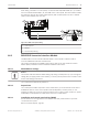


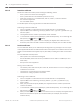


Table Of Contents
- Title Page
- Table of Contents
- Certifications, approvals, listings, and safety
- Introduction
- System overview
- Installation checklist
- Control panel installation
- Power supply
- Telephone communications
- IP communications
- Keypads, keyswitches, keyfobs and transmitters
- Keypads
- B915 Basic Keypad
- B920 Two-line Alphanumeric Keypad
- B921C Two-line Capacitive Keypad with Inputs
- B930 ATM Style Alphanumeric Keypad
- B942 Touch Screen Keypad
- Shortcuts and custom functions
- Address settings
- Supervision
- Installation and control panel wiring (keypads)
- Sensor loops overview and wiring (B921C/B942/B942W only)
- Output wiring (B942/B942W only)
- Troubleshooting
- Keyswitches
- RADION keyfobs and Inovonics pendant transmitters
- Keypads
- On-board outputs
- Off-board outputs
- On-board points
- Off-board points
- Wireless modules
- Access control
- Program and test the control panel
- Control panel board overview
- System wiring diagrams
- Approved applications
- Keypad Installer menu
- [1] Program menu
- [1] Reporting > [1] Phone menu parameters
- [1] Reporting > [2] Network menu parameters
- [1] Reporting > [3] Routing menu parameters
- [1] Reporting > [4] Personal Note menu parameters
- [2] Network > [1] Ethernet > (choose the bus module or on-board) > [1] Module Parameters menu
- [2] Network > [1] Ethernet > (choose the bus module or on-board) > [2] Address Parameters menu
- [2] Network > [1] Ethernet > (choose the bus module or on-board) > [3] DNS Parameters menu
- [2] Network > [2] Cellular > (choose the SDI2 cellular module or plug-in module)
- [3] RPS > [1] RPS Passcode menu parameters
- [3] RPS > [2] RPS Phone Number menu parameters
- [3] RPS > [3] RPS IP Address menu parameters
- [3] RPS > [4] RPS Port Number menu parameters
- [4] Area Options menu parameters
- [5] Keypad menu parameters
- [6] Users menu parameters
- [7] Points menu parameters
- [8] Disable Programming menu
- [2] Wireless menu
- [1] RF Point Menu> [1] Enroll Point RFID
- [1] RF Point Menu> [2] Replace Point RFID
- [1] RF Point Menu> [3] Remove Point RFID
- [2] RF Repeater Menu > [1] Add Repeater
- [2] RF Repeater Menu > [2] Replace Repeater
- [2] RF Repeater Menu > [3] Remove Repeater
- [3] RF Diagnostic Menu > [1] RF Points
- [3] RF Diagnostic Menu > [2] RF Repeater Menu
- [3] Diags menu
- [4] Serv Byp (Service Bypass) menu
- [5] Versions menu
- [6] Cloud menu
- [1] Program menu
- Specifications
- Appendix
- Back Page

Wireless modules
The control panel supports one B810 or one B820 for wireless sensors for easy and flexible
installation.
B810 receiver
The B810 is a wireless receiver that supports the full line of RADION wireless devices and the
RADION repeater. The receiver supports up to 504 wireless point devices, up to 1000 keyfobs,
and up to 8 repeaters.
Connect a RADION receiver SD to the SDI2 bus on the control panel using terminals PWR, A,
B, and COM. This section includes basic installation instructions. Refer to the RADION receiver
SD (B810) Installation Guide for detailed installation instructions.
SDI2 address settings
Notice!
The module reads the address switch setting only during module power up. If you change the
setting after you apply power to the module, you must cycle the power to the module in order
for the new setting to take effect.
The control panel supports only address 1.
Supervision
The control panel enables supervision of the module when you enroll at least one RF device.
Available RF devices on the control panel include RF Repeaters, wireless points, or user
keyfobs. Any failure to receive an expected response from an SDI2 module results in a system
fault display on all keypads and a fault event sent to the central station.
Installation and control panel wiring (B810)
Ensure that there is enough power for the module and other powered devices you want
connected to the system.
Refer to On-board outputs, page 60.
!
Caution!
Remove all power (AC and battery) before making any connections. Failure to do so might
result in personal injury and/or equipment damage.
Install the module
For best receiver reception results, place the receiver in a central location among the
transmitters.
1. Open the module.
2. Set the module to address 1 using the address switch.
3. Use the provided anchors and screws to mount the module base on the wall.
4. Pull the necessary wiring through the mounting plate. Refer to Wire to the control panel
(B810).
5. Install the module on the base.
Notice!
Mount the receiver in a location removed from metal. Metal objects (duct work, wire mesh
screens, boxes) reduce RF range.
14
14.1
14.1.1
14.1.2
14.1.3
72 en | Wireless modules Control Panel
2016.05 | 14 | F.01U.287.180 Installation and System Reference Guide Bosch Security Systems, Inc.